
Estimated Study Time: 15 minutes
Equipment that generate harmonics
In industrial applications, the main types of equipment that generate harmonics are: static converters, arc furnaces, lighting, saturated reactors and other equipment, such as rotating machines which generate slot harmonics (often negligible).
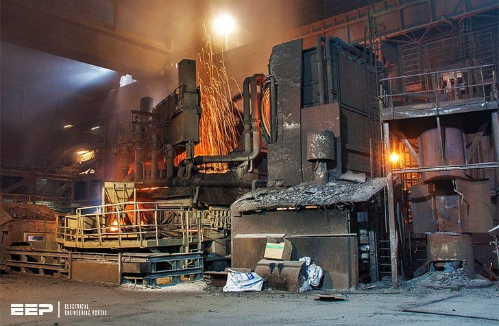 5 Main Harmonics Generators And Their Detrimental Effects On Industrial Applications (on photo: ArcelorMittal Electric Arc Furnace)
Let’s have a word about each of listed harmonics generators, calculation and their effects on industrial network.
- Harmonics generators:
- Calculation model
- Calculation method
- Principal disturbances caused by harmonic currents and voltages
1. Static converters on 3-phase networks
Rectifier bridges and, more generally, static converters (made up of diodes and thyristors) generate harmonics. For instance, to deliver a perfect DC current, a Graetz bridge requires a rectangular pulsed AC current when the load is highly inductive (see figure 1).
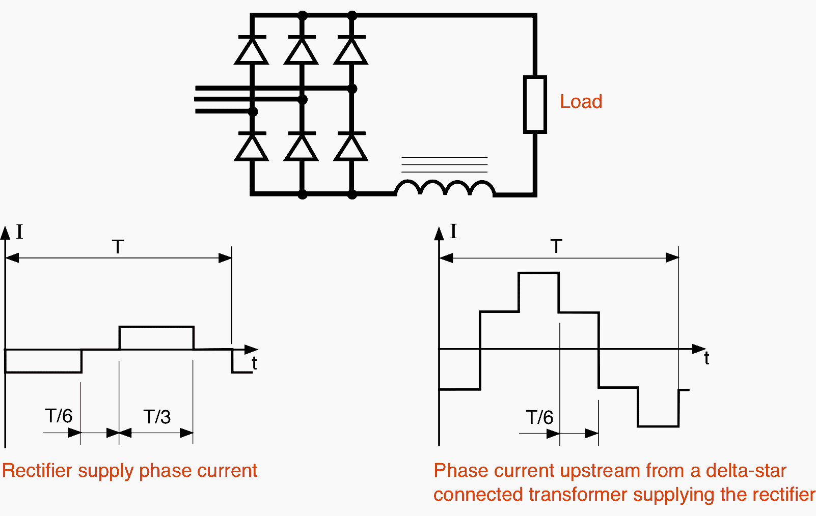
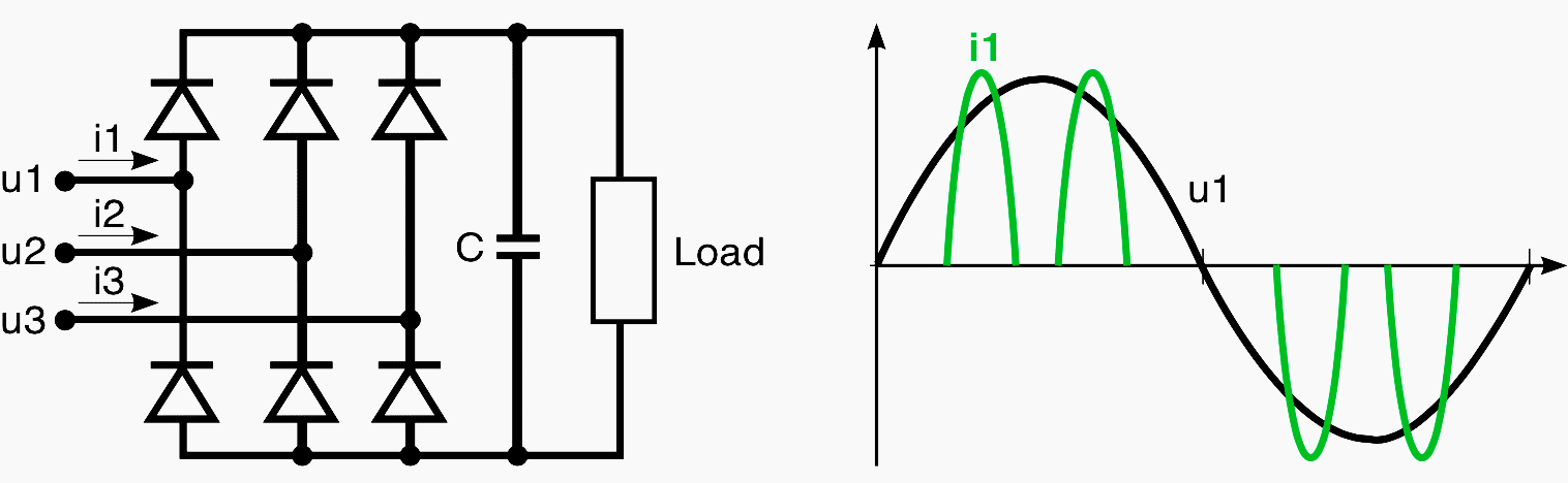
Or tips when the bridge is followed by a capacitor (see figure 2):
In spite of their different waveforms, the currents upstream and downstream from the delta-star connected transformer have the same characteristic harmonic components.
The characteristic harmonic components of the current pulses supplying rectifiers have harmonic orders n, such as n=kp±1, where:
- k = 1, 2, 3, 4, 5…
- p = number of rectifier arms, for example:
- Graetz bridge (p=6)
- 6-pulse bridge (p=6)
- 12-pulse bridge (p=12)
Applying the formula, the p = 6 rectifiers cited above generate harmonics 5, 7, 11, 13, 17, 19, 23, 25, etc., and the p = 12 rectifiers generate harmonics 11, 13, 23, 25, etc.
In practice, the current spectrum is slightly different.
New even and odd harmonics, referred to as non-characteristic harmonics, of low amplitudes, are created and the amplitudes of the characteristic harmonics are modified by several factors including:
- Asymmetry,
- Inaccuracy in thyristor firing times,
- Switching times,
- Imperfect filtering.
For thyristor bridges, a displacement of the harmonics as a function of the thyristor phase angle may also be observed.
Mixed thyristor-diode bridges generate even harmonics. They are used only at low ratings because the 2nd harmonic produces serious disturbances and is very difficult to eliminate. Other power converters such as cyclo- converters, dimmers, etc. have richer and more variable spectra than rectifiers.
Note that they are sometimes replaced by rectifiers using the PWM (Pulse Width Modulation) technique. These devices operate at high chopping frequencies (around 20 kHz) and are generally designed to generate only low levels of harmonics.
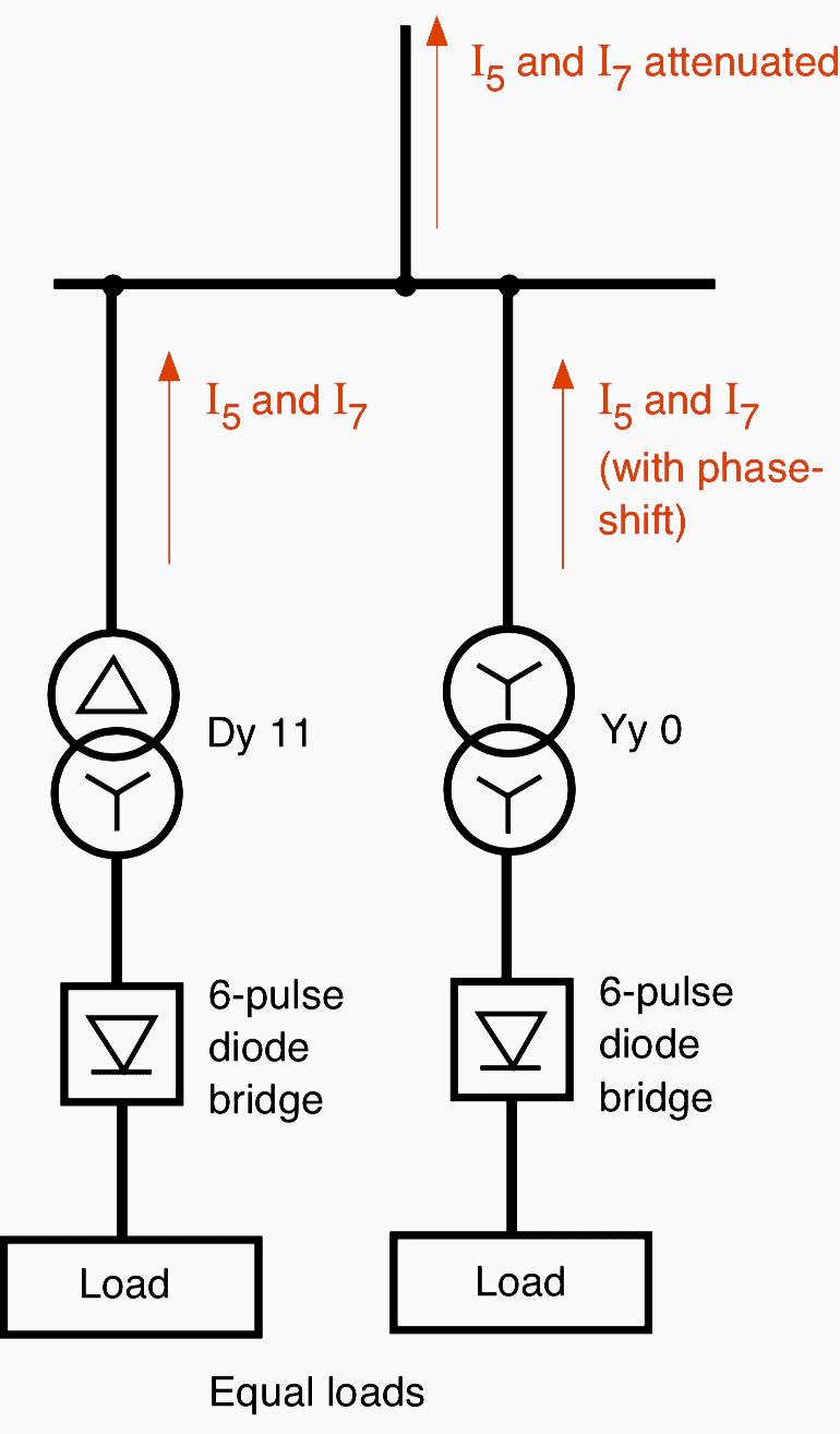
The harmonic currents of several converters combine vectorially at the common supply busbars. Their phases are generally unknown except for the case of diode rectifiers.
It is therefore possible to attenuate the 5th and 7th current harmonics using two equally loaded 6-pulse diode bridges, if the couplings of the two power supply transformers are carefully chosen (see figure 3).
2. Lighting
Lighting systems made up of discharge lamps or fluorescent lamps are generators of harmonic currents.
A 3rd harmonic ratio may even exceed 100% in certain cases of modern fluocompact lamps. The neutral conductor then carries the sum of the 3rd harmonic currents of the three phases, and may consequently be subjected to dangerous overheating if not adequately sized.
3. Arc furnaces
Arc furnaces used in the steel industry may be of the AC or DC type.
AC arc furnaces (Figure 4)
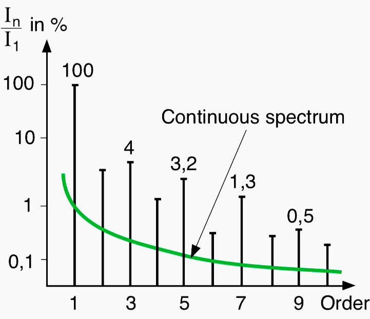
The arc is non-linear, asymmetric and unstable. It generates a spectrum including odd and even harmonics as was well as a continuous spectrum (background noise at all frequencies).
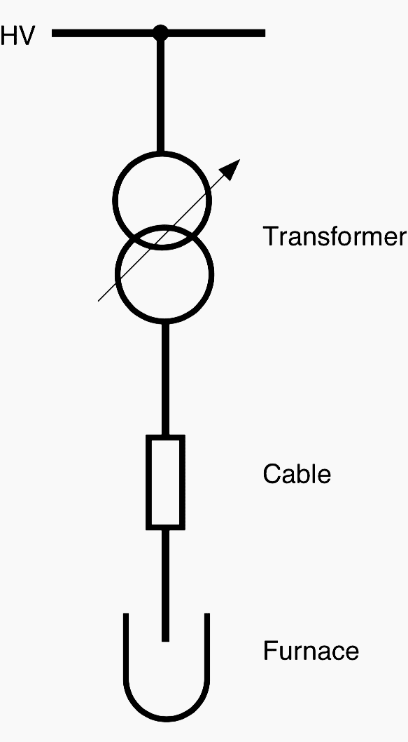
The spectrum depends on the type of furnace, its power rating and the operation considered (e.g. melting, refining). Measurements are therefore required to determine the exact spectrum (see Figure 5).
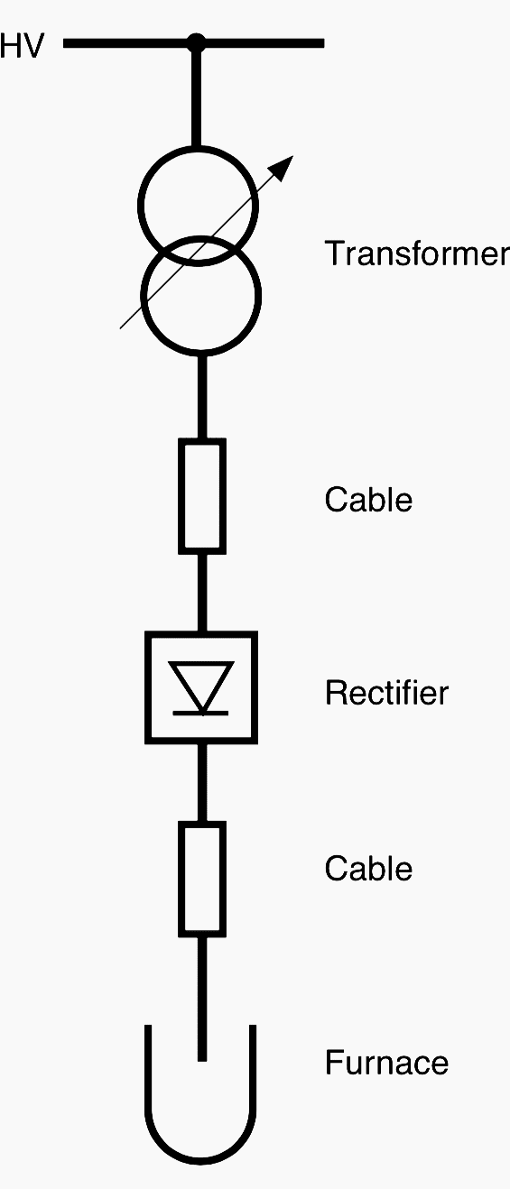
DC arc furnaces (Figure 6)
The arc is supplied via a rectifier and is more stable than the arc in AC furnaces. The current drawn can be broken down into:
- A spectrum similar to that of a rectifier,
- A continuous spectrum lower than that of an AC arc furnace.
4. Saturated reactors
The impedance of a saturable reactor is varying with the current flowing through it, resulting in considerable current distortion.
5. Rotating machines
Rotating machines generate high order slot harmonics, often of negligible amplitude. However small synchronous machines generate 3rd order voltage harmonics than can have the following detrimental effects:
- Continuous heating (without faults) of earthing resistors of generator neutrals;
- Malfunctioning of current relays designed to protect against insulation faults.
Calculation model
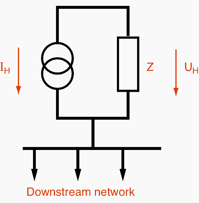
When calculating disturbances, static converters and arc furnaces are considered to be harmonic current generators (see figure 7).
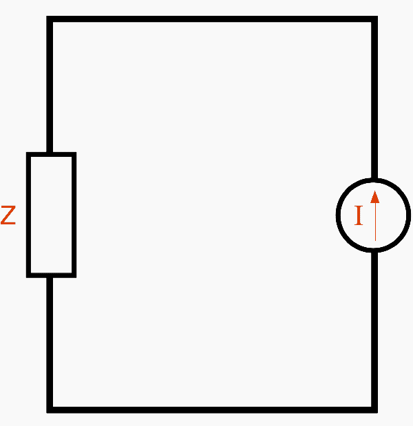
To a large extent, the harmonic currents drawn by the disturbing equipment are independent of the other loads and the overall network impedance.
The approximation is somewhat less accurate for arc furnaces. In this case, the current source model must be corrected by adding a carefully selected parallel impedance. It is also possible to take into consideration existent voltage harmonics at the connection to upstream network using the Norton equivalent model (see figure 8).
For each order of UH, the current IH is calculated taking into account Z and the downstream network impedance.
Calculation method
When harmonic current arguments (phase-shifts) are known, vector processing may be used. For a number of single phase disturbing sources, it could be of interest to use unbalanced modelling.
Interesing readings on this subject (PDF):
- Harmonic allocation using IEC/TR 61000-3-6 at the distribution/transmission interface
- The application of IEC 61000-3-6 to MV systemsin Australia
Principal disturbances caused by harmonic currents and voltages
Harmonic currents and voltages superimposed on the fundamental have combined effects on equipment and devices connected to the power supply network.
The detrimental effects of these harmonics depend on the type of load encountered, and include:
1. Instantaneous effects
Harmonic voltages can disturb controllers used in electronic systems. They can, for example, affect thyristor switching conditions by displacing the zero-crossing of the voltage wave.
Harmonics can cause additional errors in induction-disk electricity meters. For example, the error of a class 2 meter will be increased by 0.3% by a 5th harmonic ratio of 5% in current and voltage.
Ripple control receivers, such as the relays used by electrical utilities for centralized remote control, can be disturbed by voltage harmonics with frequencies in the neighbourhood of the control frequency. Other sources of disturbances affecting these relays, related to the harmonic impedance of the network, will be discussed further on.
Vibrations and noise
The electrodynamic forces produced by the instantaneous currents associated with harmonic currents cause vibrations and acoustical noise, especially in electromagnetic devices (transformers, reactors, etc.).
Interference on communication and control circuits (Telephone, control and monitoring)
Disturbances are observed when communication or control circuits are run along side power distribution circuits carrying distorted currents.
Parameters that must be taken into account include:
- The length of parallel running,
- The distance between the two circuits and
- The harmonic frequencies (coupling increases with frequency).
2. Long-term effects
Over and above mechanical fatigue due to vibrations, the main long-term effect of harmonics is heating.
Capacitor heating
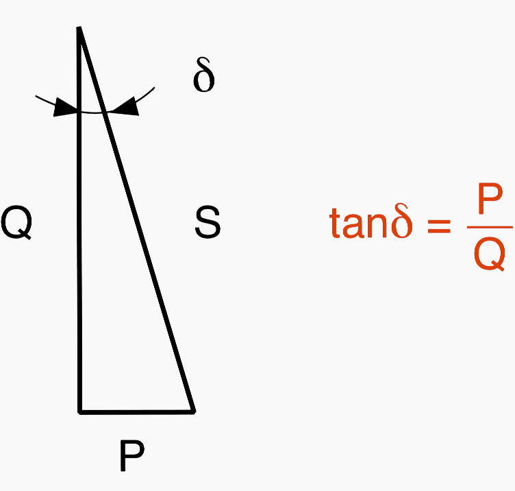
The losses causing heating are due to two phenomena: conduction and dielectric hysteresis.
These losses are defined by the loss angle δ of the capacitor, which is the angle whose tangent is the ratio of the losses to the reactive power produced (see figure 9). Values of around 10-4 may be cited for tanδ.
The heat produced can lead to dielectric breakdown.
Heating due to additional losses in machines and transformers
- Additional losses in the stators (copper and iron) and principally in the rotors (damping windings, magnetic circuits) of machines caused by the considerable differences in speed between the harmonic inducing rotating fields and the rotor. Note that rotor measurements (temperature, induced currents) are difficult if not impossible,
- Supplementary losses in transformers due to the skin effect (increase in the resistance of copper with frequency), hysteresis and eddy currents (in the magnetic circuit).
Heating of cables and equipment
Losses are increased in cables carrying harmonic currents, resulting in temperature rise. The causes of the additional losses include:
- Increase in the rms value of the current for an equal active power consumed;
- Increase in the apparent resistance of the core with frequency, due to the skin effect;
- Increase in dielectric losses in the insulation with frequency, if the cable is subjected to non- negligible voltage distortion;
- Phenomena related to the proximity of conductors with respect to metal cladding and shielding earthed at both ends of the cable, etc. Calculations for steady state can be carried out as described in IEC 60287.
Generally speaking, all electrical equipment (electrical switchboards) subjected to voltage harmonics or through which harmonic currents flow, exhibit increased energy losses and should be derated if necessary.
For example, a capacitor feeder cubicle should be designed for a current equal to 1.3 times the reactive compensation current. This safety factor does not however take into account the increased heating due to the skin effect in the conductors.
The rms value of the distorted current (or voltage) may be assessed in any of three ways:
- Measurement using a device designed to give the true rms value,
- Reconstitution on the basis of the spectrum provided by spectral analysis,
- Estimation from an oscilloscope display.
Reference // Harmonic disturbances in networks, and their treatment by Christian COLLOMBET, Jean-Marc LUPIN and Jacques SCHONEK (Schneider Electric)
Related electrical guides & articles


Edvard Csanyi
Hi, I'm an electrical engineer, programmer and founder of EEP - Electrical Engineering Portal. I worked twelve years at Schneider Electric in the position of technical support for low- and medium-voltage projects and the design of busbar trunking systems.I'm highly specialized in the design of LV/MV switchgear and low-voltage, high-power busbar trunking (<6300A) in substations, commercial buildings and industry facilities. I'm also a professional in AutoCAD programming.
Profile: Edvard Csanyi

It’s very interesting and usefull article, thank you! I’d like to know more about harmonics, do you have any good el-book or course where I could be able to improve my knowlidge?
Hi,
Please advice. How is the case when it comes to Hospital which is having lots of UPS backed up critical loads, High inrush current consuming Medical machines, VFDs and Soft starters for Mech eqt, etc? Will the harmonics be high? Can we solve them using Automatic Power factor Capacitor banks?
Plus the Hospital is 100% backed up by 11kV rated Generators, PFC are turned OFF when Generator is feeding the loads. kindly share your thoughts.
I would like to publish one of your articles in the magazine Electricity+Control. Your articles are excellent. I see that you have one on motors in hazardous areas… would it be possible for our mag to publish it? You will receive full credit for writing it. Please respond to my email address. Much appreciated.
Thank you very much for your valuable articl.would you please introduce more references or more articl/text about influences of voltage and current harmonic on the heating of HV/MV power capacitors?