Today’s mission-critical applications
In many of today’s mission-critical applications, ever-increasing reliability requirements are the norm. A critical part of this reliability is the reliability of the electric power distribution system for a given facility.
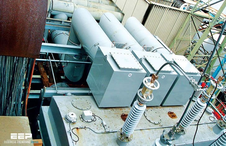
Among the most demanding applications is that of a data center, where the enduse equipment cannot tolerate even a momentary power outage and, further, even relatively minor disturbances in the power system can cause computer systems to re-boot, causing operational down-time.
That no power system component can operate with 100% reliability is a well-known fact. Another fact is that the availability of utility power is less than 100% (typically 99-99.9%).
Therefore, the possibility of utility power and internal system component failure must be taken into account in the system design.
Topologies
The choice of power system distribution topology is the first line of defense against critical-load outages.
- Secondary-Selective ‘Main-Tie-Main’ Arrangement
- Main-Tie-Main’ topology
- Ring Bus Arrangement
- Primary Loop Arrangement
- Composite Primary Loop/Secondary Selective Arrangement
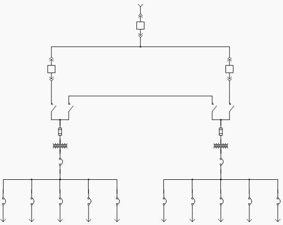
1. Secondary-Selective ‘Main-Tie-Main’ Arrangement
In the context of automatic transfers, the most common arrangement is the secondary selective or “main-tie-main” arrangement. One implementation of this arrangement is as shown in Figure 1:
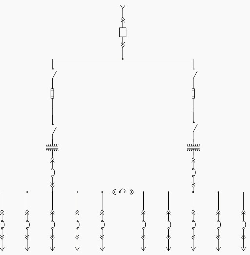
In this arrangement, there are two busses, each of which serves approximately 50% of the load, but is sized to carry the entire load. In Figure 1, this means that each transformer, secondary main circuit breaker, and secondary equipment bus is sized to carry the entire load.
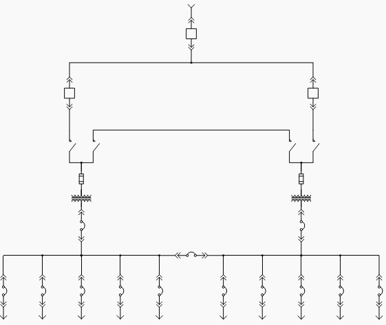
2. Main-Tie-Main’ topology
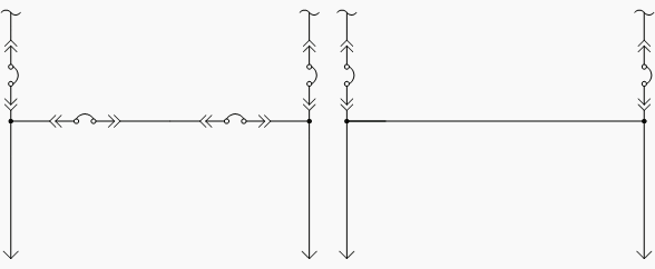
There are many variations on previous arrangement. In critical-power applications the most common variation is to use two bus tie circuit breakers, and have the two secondary busses separated into two different pieces of equipment. Another variation is the main-main arrangement, which omits the bus tie circuit breaker and simply has the two secondary busses connected all the time.
In this arrangement, one power source normally carriesthe entire load, and the other is strictly a standby power source should the normal source fail. In this way the main-main arrangement is analogous to an automatic transfer switch (ATS).
Both of these variations are shown in Figure 2.
Other arrangements exist, however none are as popular in the critical-power distribution environment as the secondary-selective “main-tie-main” and its variants.
3. Ring Bus Arrangement
One other arrangement, however, has been used with great success is the ring bus, as illustrated in Figure 3:
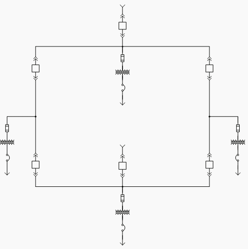
The ring bus arrangement allows the flexibility of supplying multiple loads using multiple busses. It is most often used at the medium-voltage level, and usually in a “closed loop” arrangement with all of the bus tie circuit breakers closed.
4. Primary Loop Arrangement
A variation on the ring-bus is the primary loop arrangement shown in Figure 4:
A primary loop arrangement typically uses load-interrupter switches for switching on the loop, and is more economically justifiable than a full ring-bus system. Typically, the loop is operated in an “open-loop” arrangement, but still gives the ability to supply all loads from either side of the loop.
5. Composite Primary Loop/Secondary Selective Arrangement
Extreme flexibility and increased reliability are obtained by combining topologies. An example of this is the composite primary loop/secondary-selective arrangement shown in Figure 5.
Here, multiple failure contingencies are addressed ina generally economically-feasible manner.
Reference: Critical-Power Automatic Transfer Systems – Design and Application / Bill Brown, P.E., Jay Guditis, Square D Critical Power Competency Center





The information regarding the topology is well described and it will aslo be useful but there is one thing that needs to be mentioned here is that if any layer of the topology network will fail to access then what should be done at this point? printer repair dubai has faced similar kind of disruption regarding the layers of the topology.
Hi,
Good information! I do have one question: What advantage does the primary loop arrangement have if it doesn’t have a bus tie breaker?
Can someone tell me where i can find the correct symbols for all the different protection devices? Also a set of them in CAD would also be very useful.
thanks!