
Estimated Study Time: 9 minutes
Transformer fault conditions
A number of transformer fault conditions can arise practically in any time following some special situations. These include the following five most common internal faults and few external: earth faults, core faults, interturn faults, tank faults, and external factors.
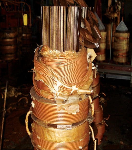
 5 common transformer fault conditions and how to protect from them (on photo: transformer winding is damaged because of lack of oil reclamaiton; credit: globecore.com)
1. Earth faults
A fault on a transformer winding will result in currents that depend on the source, neutral grounding impedance, leakage reactance of the transformer, and the position of the fault in the windings. The winding connections also influence the magnitude of fault current.
If the neutral is solidly grounded, the fault current is controlled by the leakage reactance, which depends on fault location.
The reactance decreases as the fault becomes closer to the neutral point. As a result, the fault current is highest for a fault close to the neutral point. In the case of a fault in a ∆-connected winding, the range of fault current is less than that for a Y-connected winding, with the actual value being controlled by the method of grounding used in the system.
Phase fault currents may be low for a ∆-connected winding due to the high impedance to fault of the ∆ winding. This factor should be considered in designing the protection scheme for such a winding.
Go back to transformer fault conditions ↑
2. Core faults
Core faults due to insulation breakdown can permit sufficient eddy-current to flow to cause overheating, which may reach a magnitude sufficient to damage the winding.

Go back to transformer fault conditions ↑
3. Interturn faults
Interturn faults occur due to winding flashovers caused by line surges. A short circuit of a few turns of the winding will give rise to high currents in the short-circuited loops, but the terminal currents will be low.
Go back to transformer fault conditions ↑
4. Phase-to-phase faults
Phase-to-phase faults are rare in occurrence but will result in substantial currents of magnitudes similar to earth faults.
Go back to transformer fault conditions ↑
5. Tank faults
Tank faults resulting in loss of oil reduce winding insulation as well as producing abnormal temperature rises.

Go back to transformer fault conditions ↑
External factors
In addition to fault conditions within the transformer, abnormal conditions due to external factors result in stresses on the transformer.
These conditions include:
- Overloading,
- System faults,
- Overvoltages, and
- Under-frequency operation.
Magnetizing inrush current
When a transformer is switched in at any point of the supply voltage wave, the peak values of the core flux wave will depend on the residual flux as well as on the time of switching. The peak value of the flux will be higher than the corresponding steady-state value and will be limited by core saturation.
Maximum inrush occurs if the transformer is switched in when the supply voltage is zero. Realizing this, is important for the design of differential relays for transformer protection so that no tripping takes place due to the magnetizing inrush current. A number of schemes based on the harmonic properties of the inrush current are used to prevent tripping due to large inrush currents.
Overheating protection
Overheating protection is provided for transformers by placing a thermal-sensing element in the transformer tank.
Overcurrent relays are used as a backup protection with time delay higher than that for the main protection.
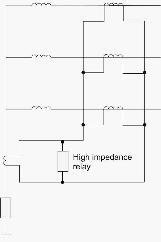
Restricted earth fault protection is utilized for Y-connected windings. This scheme is shown in Figure 4. The sum of the phase currents is balanced against the neutral current, and hence the relay will not respond to faults outside the winding.
Differential protection is the main scheme used for transformers. The principle of a differential protection system is simple. Here the currents on each side of the protected apparatus for each phase are compared in a differential circuit. Any difference current will operate a relay.
Figure 5 shows the relay circuit for one phase only. On normal operation, only the difference between the current transformer magnetizing currents 1 m i and 2 m i passes through the relay.
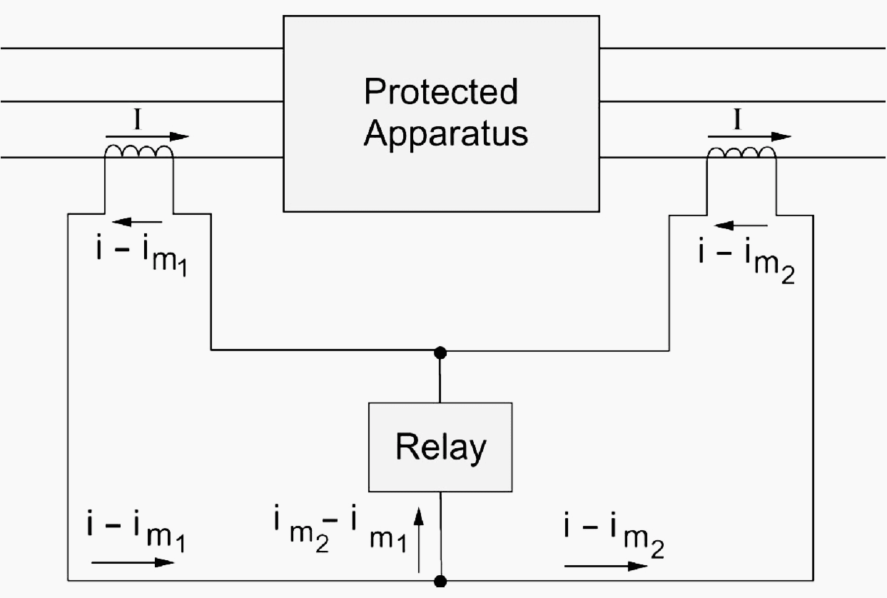
This is due to the fact that with no faults within the protected apparatus, the currents entering and leaving are equal to i. If a fault occurs between the two sets of current transformers, one or more of the currents (in a three-phase system) on the left-hand side will suddenly increase, while that on the right-hand side may decrease or increase with a direction reversal. In both instances, the total fault current will flow through the relay, causing it to operate.
In units where the neutral ends are inaccessible, differential relays are not used, but reverse power relays are employed instead.
A number of considerations should be dealt with in applying differential protection, including:
- Transformer ratio: The current transformers should have ratings to match the rated currents of the transformer winding to which they are applied.
- Due to the 30°-phase change between Y-connected and ∆-connected windings and the fact that zero sequence quantities on the Y side do not appear on the terminals of the ∆ side, the current transformers should be connected in Y for a ∆ winding and in ∆ for a Y winding.

Figure 6 – Differential Protection of a ∆/Y Transformer Figure 6 shows the differential protection scheme applied to a ∆/Y transformer. When current transformers are connected in ∆, their secondary ratings must be reduced to 1/√3 times the secondary rating of Y-connected transformers.
- Allowance should be made for tap changing by providing restraining coils (bias). The bias should exceed the effect of the maximum ratio deviation.

Go back to transformer fault conditions ↑
Reference // Electrical Energy Systems by Mohamed E. El-Hawary (Purchase hardcopy from Amazon)
Related electrical guides & articles


Edvard Csanyi
Hi, I'm an electrical engineer, programmer and founder of EEP - Electrical Engineering Portal. I worked twelve years at Schneider Electric in the position of technical support for low- and medium-voltage projects and the design of busbar trunking systems.I'm highly specialized in the design of LV/MV switchgear and low-voltage, high-power busbar trunking (<6300A) in substations, commercial buildings and industry facilities. I'm also a professional in AutoCAD programming.
Profile: Edvard Csanyi

Nice article; however, it will be more comprehensive if all possible internal and external fault factors are discussed.
Some of the common internal causes include:
Paper Insulation Breakdown
Oil Contamination
Moisture
Overloading
Partial Discharge
Loose Connections
Core Faults
Abnormal Conditions due toExternal Factors:
System Faults
Lightning
Overvoltages
Under-frequency Operation
Design and Material Flaws
Fire
Flood
like to read electrical papers
Nice information.
Sir,If earth-fault occurs neaby eletrical system of Power transformer. The power transformer is not feeding the said electrical system. Then what will be the impact of earth-fault on power transformer? Will REF protetion of power transformer operate? or which protetion of power transformer operate?
free hand sketch
I can find no where that there is a written technical answer. I assume you have the total experience to give that answer. Simple question but no where is there a specific answer.
Question : How do you size the secondary conductors for a transformer rated OA / FA/ FOA , 55/65 C. And can you give technical reference. Or is this based on the load and what the load varation.
I will take premium membership if you will answer the following question. I can find no where that there is a written technical answer. I assume you have the total experience to give that answer. Simple question but no where is there a specific answer.
Question : How do you size the secondary conductors for a transformer rated OA / FA/ FOA , 55/65 C. And can you give technical reference. Or is this based on the load and what the load varation.
Vous êtes le meilleur.
Issue about earth fault in a transformer. In your article,
” the fault current is highest for a fault close to the neutral point”, When the fault is near the neutral point, the winding impedance may be getting smaller. But at the same time, the voltage developed from the winding is getting smaller as well. So the fault current is small due to low winding voltage, it is not largest value of fault current, and it may be near zero in fault current.
Good article, basic but clear for many. It is missing over fluxing relay (24). It could be important also to mention as I call “mechanical protection for transformers”; i.e. Buchholz, high pressure, oil level and temperature.