
Estimated Study Time: 5 minutes
Dangerous voltages in substation
Figures 1 and 2 show the voltages a person can be exposed to in a substation. There are many definitions related to these voltages, but the following six are the most important.
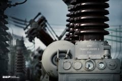
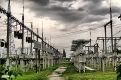
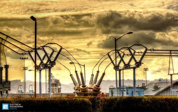 5 Voltages a Person Can Be Exposed To In a Substation (photo credit: Terry F Luehmann via Flickr)
These definitions are:
- Ground potential rise (GPR)
- Mesh voltage
- Metal-to-metal touch voltage
- Step voltage
- Touch voltage
- Transfer red voltage
1. Ground potential rise (GPR)
The maximum electrical potential that a substation grounding grid may attain relative to a distant grounding point assumed to be at the potential of remote earth. Ground potential rise is the product of the magnitude of the grid current, the portion of the fault current conducted to earth by the grounding system, and the ground grid resistance.

Go back to Dangerous Voltages ↑
2. Mesh voltage
The maximum touch voltage within a mesh of a ground grid.
The actual mesh voltage, Em (maximum touch voltage), is the product of the soil resistivity, ρ; the geometrical factor based on the configuration of the grid, Km; a correction factor, Ki, which accounts for some of the errors introduced by the assumptions made in deriving Km; and the average current per unit of effective buried length of the conductor that makes up the grounding system (IG/LM):
3. Metal-to-metal touch voltage
The difference in potential between metallic objects or structures within the substation site that can be bridged by direct hand-to-hand or hand-to-feet contact.
Important Note //
The metal-to-metal touch voltage between metallic objects or structures bonded to the ground grid is assumed to be negligible in conventional substations.
However, the metal-to-metal touch voltage between metallic objects or structures bonded to the ground grid and metallic objects inside the substation site but not bonded to the ground grid, such as an isolated fence, may be substantial.
Go back to Dangerous Voltages ↑
4. Step voltage
Step voltage is actually the difference in surface potential experienced by a person bridging a distance of 1 m with the feet without contacting any other grounded object.
Go back to Dangerous Voltages ↑
5. Touch voltage
Touch voltage is the potential difference between the ground potential rise and the surface potential at the point where a person is standing while at the same time having a hand in contact with a grounded structure.
Go back to Dangerous Voltages ↑
6. Transfer red voltage
A special case of the touch voltage where a voltage is transferred into or out of the substation, from or to a remote point external to the substation site. The maximum voltage of any accidental circuit must not exceed the limit that would produce a current flow through the body that could cause fibrillation.
Assuming the more conservative body weight of 50 kg to determine the permissible body current and a body resistance of 1000 V, the tolerable touch voltage is:
and the tolerable step voltage is:

where //
- Estep – Step voltage, V
- Etouch – Touch voltage, V
- rs – Resistivity of the surface material, V-m
- ts – Duration of shock current, in seconds
Since the only resistance for the metal-to-metal touch voltage is the body resistance, the voltage limit is:

The shock duration is usually assumed to be equal to the fault duration. If re-closing of a circuit is planned, the fault duration time should be the sum of the individual faults and used as the shock duration time ts.
Go back to Dangerous Voltages ↑
Reference: The electric power engineering handbook – L.L. Grigsby (Purchase hardcover book from Amazon)
Related electrical guides & articles


Edvard Csanyi
Hi, I'm an electrical engineer, programmer and founder of EEP - Electrical Engineering Portal. I worked twelve years at Schneider Electric in the position of technical support for low- and medium-voltage projects and the design of busbar trunking systems.I'm highly specialized in the design of LV/MV switchgear and low-voltage, high-power busbar trunking (<6300A) in substations, commercial buildings and industry facilities. I'm also a professional in AutoCAD programming.
Profile: Edvard Csanyi

Dear Edvard,
This is very important and helpful information that you shared.
Thank you.
I m a commissioning engineer and i highly value ur article for me as well as for all substation related personnels.
Thanks.
Dear Edvard Casany,
it is a very important hint to people who go in the operation group. So I can just appeal all those who delegate an engineer for an Operational work he must take your article in his laptop! A good job indeed, dear colleague!
Dear Edward!
Good Morning!
Your articles are very nice. It is very useful to gain more knowledge for all electrical engineering persons.
Thank You
Great article