
Estimated Study Time: 16 minutes
Wiring and grounding problems
In this technical article, typical wiring and grounding problems, as related to power quality, are presented. Possible solutions are given for these problems as well as the possible causes for the problems being observed on the grounding system. (See Table 2 at the bottom of article)
 6 wiring and grounding problems that lead to low power quality
The following list is just a sample of problems that can occur on the grounding system.
- Isolated grounds
- Ground loops
- Missing safety ground
- Multiple neutral-to-ground bonds
- Additional ground rods
- Insufficient neutral conductors
1. Insulated grounds
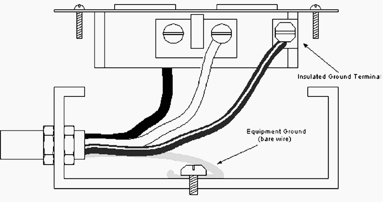
Insulated grounds in themselves are not a grounding problem. However, improperly used insulated grounds can be a problem. Insulated grounds are used to control noise on the grounding system. This is accomplished by using insulated ground receptacles, which are indicated by a “∆” on the face of the outlet.
Insulated ground receptacles are often orange in color. Figure 1 illustrates a properly wired insulated ground circuit.
The NEC has this to say about insulated grounds.
NEC 250-74 Connecting receptacle grounding terminal to box
An equipment bonding jumper shall be used to connect the grounding terminal of a grounding-type receptacle to a grounded box.
Exception No. 4. Where required for the reduction of electrical noise (electromagnetic interference) on the grounding circuit, a receptacle in which the grounding terminal is purposely insulated from the receptacle mounting means shall be permitted. The receptacle grounding terminal shall be grounded by an insulated equipment grounding conductor run with the circuit conductors. This grounding conductor shall be permitted to pass through one or more panelboards without connection to the panelboard grounding terminal as permitted in Section 384-20, Exception so as to terminate within the same building or structure directly at an equipment grounding conductor terminal of the applicable derived system or source.
(FPN): Use of an isolated equipment grounding conductor does not relieve the requirement for grounding the raceway system and outlet box.
NEC 517-16 Receptacles with insulated grounding terminals
Receptacles with insulated grounding terminals, as permitted in Section 250-74, Exception No. 4, shall be identified. Such identification shall be visible after installation.
(FPN): Caution is important in specifying such a system with receptacles having insulated grounding terminals, since the grounding impedance is controlled only by the grounding conductors and does not benefit functionally from any parallel grounding paths.
The following is a list of pitfalls that should be avoided when installing insulated ground circuits:
- Running an insulated ground circuit to a regular receptacle.
- Sharing the conduit of an insulated ground circuit with another circuit.
- Installing an insulated ground receptacle in a two-gang box with another circuit.
- Not running the insulated ground circuit in a metal cable armor or conduit.
- Do not assume that an insulated ground receptacle has a truly insulated ground.
Go back to Wiring and Grounding Problems ↑
2. Ground loops
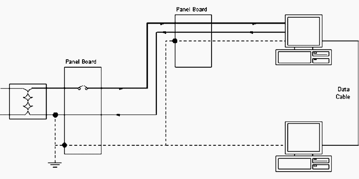
Ground loops can occur for several reasons. One is when two or more pieces of equipment share a common circuit like a communication circuit, but have separate grounding systems (Figure 2).
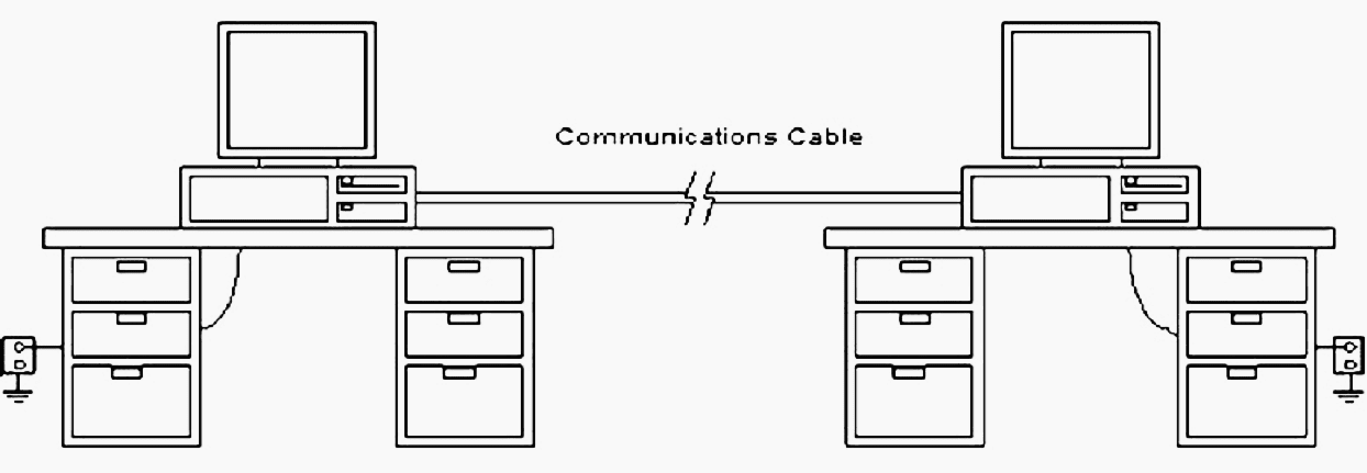
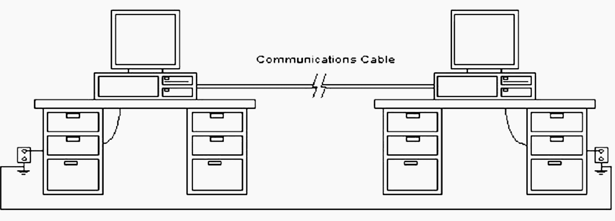
To avoid this problem, only one ground should be used for grounding systems in a building. More than one grounding electrode can be used, but they must be tied together (NEC 250-81, 250-83, and 250-84) as illustrated in Figure 3 below.
Go back to Wiring and Grounding Problems ↑
3. Missing safety ground
A missing safety ground poses a serious problem. Missing safety grounds usually occur because the safety ground has been bypassed. This is typical in buildings where the 120-volt outlets only have two conductors.
This device allows the use of a three-prong device in a two-prong outlet. When properly connected, the safety ground remains intact. Figure 4 illustrates the proper use of the cheater plug.

If an equipment ground is not present in the outlet box, then the grounding plug adapter should not be used. If the equipment grounding conductor is present, the preferred method for solving the missing safety ground problem is to install a new three-prong outlet in the outlet box.
This method insures that the grounding conductor will not be bypassed. The NEC discusses equipment grounding conductors in detail in Section 250 — Grounding.
Go back to Wiring and Grounding Problems ↑
4. Multiple neutral to ground bonds
Another misconception when grounding equipment is that the neutral must be tied to the grounding conductor. Only one neutral-to-ground bond is permitted in a system or sub-system. This typically occurs at the service entrance to a facility unless there is a separately derived system.
The neutral should be kept separate from the grounding conductor in all panels and junction boxes that are downline from the service entrance. Extra neutral-to-ground bonds in a power system will cause neutral currents to flow on the ground system.
This flow of current on the ground system occurs because of the parallel paths. Figures 5 and 6 illustrate this effect.
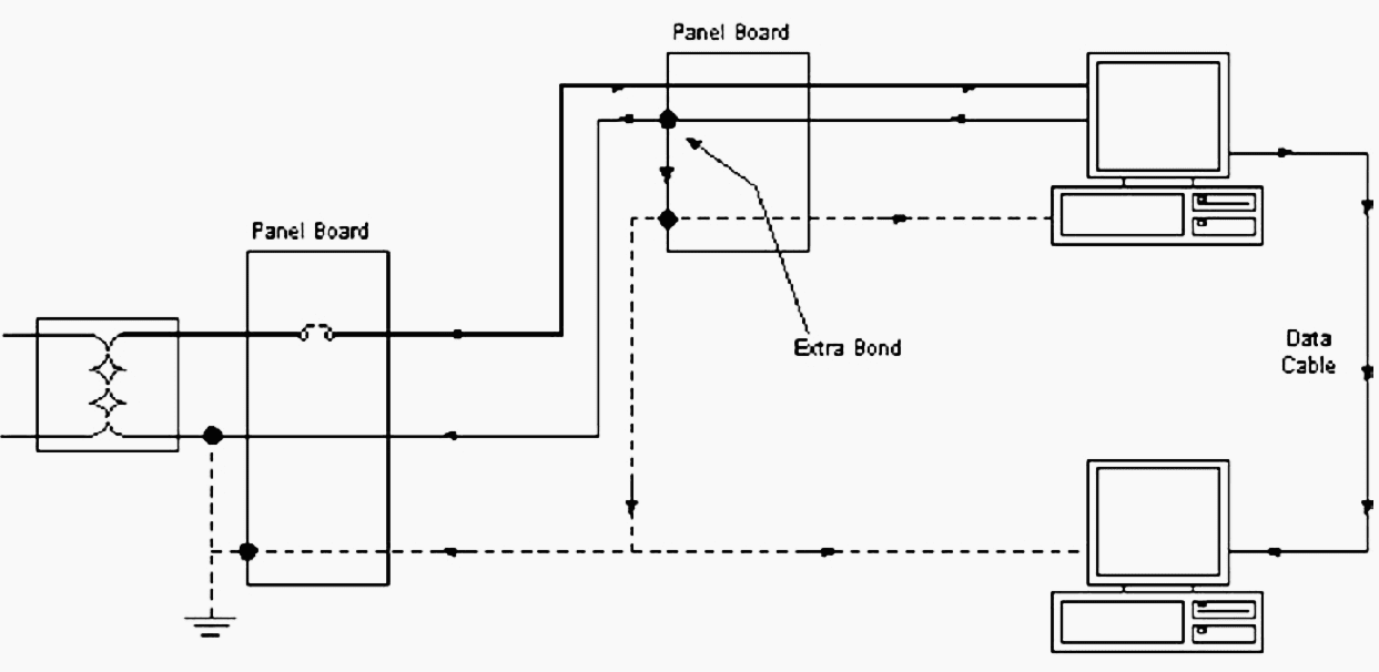
As seen in Figure 6, neutral current can find its way onto the ground system due to the extra neutral-to-ground bond in the secondary panel board. Notice that not only will current flow in the ground wire for the power system, but currents can flow in the shield wire for the communication cable between the two PCs.
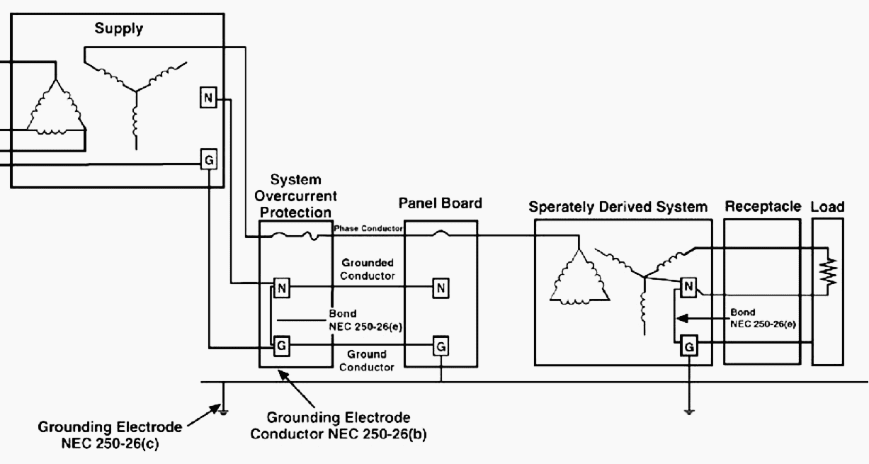
If the neutral-to-ground bond needs to be reestablished (high neutral-to-ground voltages), this can be accomplished by creating a separately derived system as defined above. Figure 7 illustrates a separately derived system.
Go back to Wiring and Grounding Problems ↑
5. Additional ground rods
Additional ground rods are another common problem in grounding systems. Ground rods for a facility or building should be part of the grounding system. The ground rods should be connected where all the building grounding electrodes are bonded together.
Isolated grounds can be used as described in the NEC’s Isolated Ground section, but should not be confused with isolated ground rods, which are not permitted.
However, if there is more than one ground rod for the facility, the transient current enters the facility’s grounding system at more than one location and a portion of the transient current will flow on the grounding system causing the ground potential of equipment to rise at different levels.
This, in turn, can cause severe transient voltage problems and possible conductor overload conditions!
Go back to Wiring and Grounding Problems ↑
6. Insufficient neutral conductor
With the increased use of electronic equipment in commercial buildings, there is a growing concern for the increased current imposed on the grounded conductor (neutral conductor). With a typical three-phase load that is balanced, there is theoretically no current flowing in the neutral conductor, as illustrated in Figure 8.
However, PCs, laser printers, and other pieces of electronic office equipment all use the same basic technology for receiving the power that they need to operate. Figure 9 illustrates the typical power supply of a PC. The input power is generally 120 volts AC, single phase.
The internal electronic parts require various levels of DC voltage (e.g., ± 5, 12 volts DC) to operate.
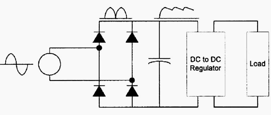
This DC voltage is obtained by converting the AC voltage through some type of rectifier circuit as shown. The capacitor is used for filtering and smoothing the rectified AC signal. These types of power supplies are referred to as switch mode power supplies (SMPS).
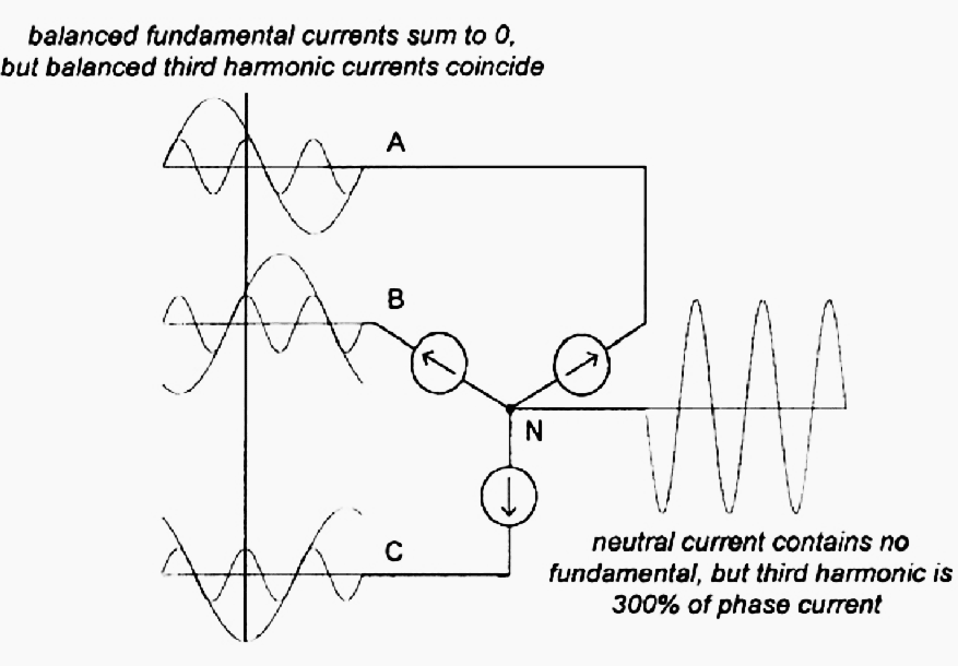
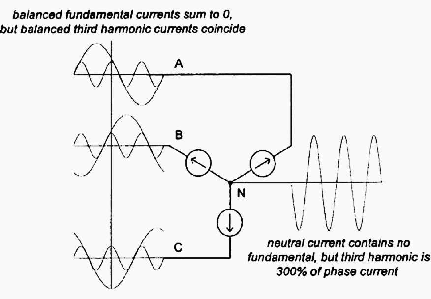
Triplen harmonics are those that are odd multiples of the fundamental frequency component (h = 3, 9, 15, 21, …). For a system that has balanced single-phase loads as illustrated in Figure 10, fundamental and third harmonic components are present.
Applying Kirchoff’s current law at node N shows that the fundamental current component in the neutral must be zero. But when loads are balanced, the third harmonic components in each phase coincide. Therefore, the magnitude of third harmonic current in the neutral must be three times the third harmonic phase current.
This becomes a problem in office buildings when multiple single-phase loads are supplied from a three-phase system. Separate neutral wires are run with each circuit, therefore the neutral current will be equivalent to the line current.
If office partitions are used, the same, often undersized neutral conductor is run in the partition with three-phase conductors. Each receptacle is fed from a separate phase in order to balance the load current.
NOTE! However, a single neutral is usually shared by all three phases. This can lead to disastrous results if the partition electrical receptacles are used to supply nonlinear loads rich in triplen harmonics. Under the worst conditions, the neutral current will never exceed 173% of the phase current.
Figure 10 illustrates a case where a three-phase panel is used to serve multiple single-phase SMPS PCs.
Go back to Wiring and Grounding Problems ↑
Summary
As discussed above, the three main reasons for grounding in electrical systems are:
- Personal safety
- Proper protective device operation
- Noise control
By following the guidelines found below, the objectives for grounding can be accomplished:
- All equipment should have a safety ground. A safety ground conductor
- Avoid load currents on the grounding system.
- Place all equipment in a system on the same equipotential reference.
Table 1 summarizes typical wiring and grounding issues.
Table 1 – Summary of wiring and grounding issues
| Summary Issues |
| Good power quality and noise control practices do not conflict with safety requirements. |
| Wiring and grounding problems cause a majority of equipment interference problems. |
| Make an effort to put sensitive equipment on dedicated circuits. |
| The grounded conductor, neutral conductor, should be bonded to the ground at the transformer or main panel, but not at other panel down line except as allowed by separately derived systems. |
Table 2 – Typical wiring and grounding problems and causes
| Wiring Condition or Problem Observed | Possible Cause |
| Impulse, voltage drop out | Loose connections |
| Impulse, voltage drop out | Faulty breaker |
| Ground currents | Extra neutral-to-ground bond |
| Ground currents | Neutral-to-ground reversal |
| Extreme voltage fluctuations | High impedance in neutral circuit |
| Voltage fluctuations | High impedance neutral-to-ground bonds |
| High neutral to ground voltage | High impedance ground |
| Burnt smell at the panel, junction box, or load | Faulted conductor, bad connection, arcing, or overloaded wiring |
| Panel or junction box is warm to the touch | Faulty circuit breaker or bad connection |
| Buzzing sound | Arcing |
| Scorched insulation | Overloaded wiring, faulted conductor, or bad connection |
| Scorched panel or junction box | Bad connection, faulted conductor |
| No voltage at load equipment | Tripped breaker, bad connection, or faulted conductor |
| Intermittent voltage at the load equipment | Bad connection or arcing |
Go back to Wiring and Grounding Problems ↑
Reference // Halpin, S.M.“Power Quality”; The Electric Power Engineering Handbook by Ed.L.L. Grigsby (Purchase hardcover from Amazon)
Related electrical guides & articles


Edvard Csanyi
Hi, I'm an electrical engineer, programmer and founder of EEP - Electrical Engineering Portal. I worked twelve years at Schneider Electric in the position of technical support for low- and medium-voltage projects and the design of busbar trunking systems.I'm highly specialized in the design of LV/MV switchgear and low-voltage, high-power busbar trunking (<6300A) in substations, commercial buildings and industry facilities. I'm also a professional in AutoCAD programming.
Profile: Edvard Csanyi

All the electrical work at this facility looks commercial grade but the equipment picks up ghost ground wire problems and your article has identified the most likely reasons. Thank you. I’m ASE certified in automotive heating and air also residential and commercial heating and air. We are constantly trying to find the electrical issues with all the broken equipment. I was a microwave radio repairman in the military. Now I’m doing emission testing and the Smog Tamer computer is failing a lot of vehicles which otherwise would have passed.
Thanks Edvard for this information.
Edvard. thanks for the information ,I am a mechanical enginner ,68 years old. retired but I still learning .because I need to stay on tuning on this matter…