Transmission Line Insulator Flashovers
Contamination caused insulator flashovers produce frequent outages in severely contaminated areas. Lines closer to the ocean are in more danger of becoming contaminated. Several countermeasures have been proposed to improve insulator performance.

The most frequently used methods are:
- Increasing leakage distance
- Semiconducting glaze
- Periodic washing
- Periodic cleaning
- Replacement
- Covering with silicon rubber
- Covering with petroleum
1. Increasing leakage distance
Increasing leakage distance by increasing the number of units or by using fog-type insulators.
The disadvantages of the larger number of insulators are that both the polluted and the impulse flashover voltages increase. The latter jeopardizes the effectiveness of insulation coordination because of the increased strike distance, which increases the overvoltages at substations.


2. Semiconducting glaze
Application insulators are covered with a semiconducting glaze.
A constant leakage current flows through the semiconducting glaze. This current heats the insulator’s surface and reduces the moisture of the pollution. In addition, the resistive glaze provides an alternative path when dry bands are formed. The glaze shunts the dry bands and reduces or eliminates surface arcing. The resistive glaze is exceptionally effective near the ocean.
3. Periodic washing
Periodic washing of the insulators with high-pressure water.
The transmission lines are washed by a large truck carrying water and pumping equipment. Trained personnel wash the insulators by aiming the water spray toward the strings. Substations are equipped with permanent washing systems. High-pressure nozzles are attached to the towers and water is supplied from a central pumping station.
However, major drawbacks of this method include high installation and operational costs.
4. Periodic cleaning
Periodic cleaning of the insulators by high pressure driven abrasive material.
Periodic cleaning by materials such as ground corn cobs or walnut shells. This method provides effective cleaning, but cleaning of the residual from the ground is expensive and environmentally undesirable.
5. Replacement
Replacement of porcelain insulators with non-ceramic insulators
Non-ceramic insulators have better pollution performance, which eliminates short-term pollution problems at most sites. However, insulator aging may affect the long-term performance.


6. Covering with silicon rubber
Covering the insulators with a thin layer of room-temperature vulcanized (RTV) silicon rubber coating.
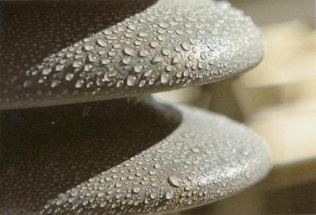
This coating has a hydrophobic and dirt-repellent surface, with pollution performance similar to non-ceramic insulators. Aging causes erosion damage to the thin layer after 5-10 years of operation. When damage occurs, it requires surface cleaning and a reapplication of the coating.
Cleaning by hand is very labor intensive. The most advanced method is cleaning with high pressure driven abrasive materials like ground corn cobs or walnut shells. The coating is sprayed on the surface using standard painting techniques.


7. Covering with petroleum
Covering the insulators with a thin layer of petroleum or silicon grease.
Grease provides a hydrophobic surface and absorbs the pollution particles. After one or two years of operation, the grease saturates the particles and it must be replaced. This requires cleaning of the insulator and application of the grease, both by hand.
Because of the high cost and short life span of the grease, it is not used anymore.
Reference: The electric power engineering handbook – L.L. Grigsby (Purchase hardcover book from Amazon)


Reasons for flash over of top disc insulators in 132kv lines
I have been interested with your points on how to reduce insulator flash over in TL. Hence iam working with electrical company as the live line personnel I would like to know if you have a room for training so that I can organise my training on your company especially washing and replacement of insulators. Thank you.
How to create super hydrophobic effect on porcelain surface insulators ( before firing or after fired insulators)
Hallo Sirs,
How to recognize when the changes have taken place before damage occurs?
Do you know any predictive maintanance system for it?
And aspecily it can permanently work on under voltage and switched off over head HV power lines.
Regard,
Greg
Bhutan
Sir,
We are experincing frequent flashover and snapping of twin moose conductor in a 400kV tension line at the same location.
We are using glass insulators.
How to improve this? If we provide additional earth.. will this improve?
Thanks for your comments
Please advise me that for removing the contamination and dirt from the insulators (25 KVA) in the roof of electric locomotives by spraying dry ice (CO2) is permitted or not?
BEST REGARDS
hello sir;
I have question,
What is water /Solvent use for cleaning insulator ?
Good
No word to tell about your transparency, i am also one of the electrical lover.
Thank you RADHAKRISHNAN!
Hi Mr csanyi I have question we have 2 kilometer 33 kv cable 3*300 we want to test this cable with hipot test and apply 76 kv dc voltage how much kva hipot instrument we need thanks for answer me?
Hai Mr.Behnam Baradaran,
Since the test voltage is DC,the high voltage supply requirs only charging current along with the leakage current of the cable.By slowly increasing the testvoltage,the charging can be reduced to a very low value.Thenthe Dc supply has to drive only the leakage current of the cable.I feel even with a10 -15 mA current capacity is adequate
regards,
nambudiri..
hello sir
Hipot is in measuring terms voltage and joules actually 32 KV 2500 j