High Voltage Direct Current (HVDC)
Few weeks back I posted an article about advantages of HVDC over HVAC transmission systems. Advantages of HVDC are numerous and very well recognized, but like everything on this earth this system has other side too.
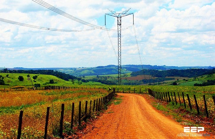
The eight main disadvantages of HVDC transmission systems, including DC links connecting HVAC systems area, are summarized and briefly explained below:
Disadvantage #1 (expensive)
Converter stations needed to connect to AC power grids are very expensive.
Converter substations are more complex than HVAC substations, not only in additional converting equipment, but also in more complicated control and regulating systems.
Disadvantage #2 (complex)
In contrast to AC systems, designing and operating multi-terminal HVDC systems is complex.
Controlling power flow in such systems requires continuous communication between all terminals, as power flow must be actively regulated by the control system instead of by the inherent properties of the transmission line.
Disadvantage #3 (expensive again)
Converter substations generate current and voltage harmonics, while the conversion process is accompanied by reactive power consumption. As a result, it is necessary to install expensive filter-compensation units and reactive power compensation units.
Disadvantage #4 (power faults)
During short-circuits in the AC power systems close to connected HVDC substations, power faults also occur in the HVDC transmission system for the duration of the short-circuit.
During short-circuits on the inverter output side, a full HVDC transmission system power fault can be caused. Power faults due to short-circuits on the rectifier input side are usually proportional to the voltage decrease.
Disadvantage #5 (capacities)
The number of substations within a modern multi-terminal HVDC transmission system can be no larger than six to eight, and large differences in their capacities are not allowed. The larger the number of substations, the smaller may be the differences in their capacities.
Thus, it is practically impossible to construct an HVDC transmission system with more than five substations.
Disadvantage #6 (radio noise)
The high-frequency constituents found in direct current transmission systems can cause radio noise in communications lines that are situated near the HVDC transmission line.
Disadvantage #7 (dificult grounding)
Grounding HVDC transmission involves a complex and difficult installation, as it is necessary to construct a reliable and permanent contact to the Earth for proper operation and to eliminate the possible creation of a dangerous “step voltage.”
Disadvantage #8
The flow of current through the Earth in monopole systems can cause the electro-corrosion of underground metal installations, mainly pipelines.
Conclusion
Some of the above-listed disadvantages can be eliminated with the use of new technologies. In particular, disadvantages such as a complete power fault of the HVDC transmission system during short-circuits inthe AC power system and reactive power consumption can be eliminated completely, or mostly, with the use of turn-off thyristors.
Several research centers are working on improving high-capacity turn-off thyristors and also on new types of converter devices for high-capacity HVDC transmission.
Finally, there are several new techniques for the perfection of grounding devices, providing for decreased electro-corrosion impacts and the formation of so-called “metal return”, which precludes the working current from flowing through the ground. Other techniques aimed
at perfecting HVDC technology are also being developed (Koshcheev 2001).
Reference: Argonne National Laboratory – The design, construction and operation of long-distance high voltage electricity transmission technologies





The losses in long distance electrical power transmission lines come from electricity elost due to resistance of the transimission line.
If P is the power transmitted, and R is the resistance of the line:
P = IV
P_{loss} = I^2R = P^2R/V^2
If P is fixed by community demand, then can reduce lost power by increasing the transmission voltage. As a result, all long-distance power transmission, AC or DC, is done at high voltage.
Nice detail.But I want the detail of the converter part if you are willing.
For #2: It’s a bit too early to talk multi-terminal, since we still don’t have effective DC breakers can deal with high ratings.
For #3: Not if you are using MMC VSC-HVDC with sufficient levels (e.g. 401). There is one already built by Siemens in the U.S.
For #4: At cases like this, the converter will be blocked. And it is actually reasonbly fast, compared with AC breakers. Although, I do recongize that the link will be discharging which could bring all sorts of problems.
For #5: This is too early to say. Technologies will be improved. Just back in 2010, who would imagine that VSC-HVDC can now operate at 1 GW?
For #6: I think a good old fashion Faraday cage shielding structure can reduce a significant amount of it. And if the communication lines are optic based, the influence should be minimal.
For #7: Agreed. Especially for transformers.
For #8: For symmetrical monopole (which is the main stream) and bipolar (not a lot), this is not a major problem, since the earth current should be largely cancelled. Although these schemes do run at ground return mode during mainteance. The concern for ground current is actually more on the neighbouring AC transformers.
First of all thank you for the article.
Can you elaborate the point no. 7 ??
how the HVDV grounding is difficult compared to HVAC?
If you need to compare HVDC with HVAC from power system operation point of view Please press the below links to compare them in a real time simulation
ACTUAL SIMULATION: http://www.intelectri.com/linkedin/POUYAk.BAT
INFORMATION OF NETWORK: http://www.intelectri.com/NETWORK/k/IN.pdf
If you choose the ACTUAL SIMULATION link, a small batch file will be downloaded. Press on this batch file to start the HVDC example network real time simulation, if you have already have POUYA software installed on your computer. Otherwise it will guide you to install POUYA software. Alternatively you can visit http://www.intelectri.com for free downloading POUYA software. (Note that: clicking on the first link above will download an open source batch file (1KB). Windows operating system will usually warn you about the danger of any batch file running on computer.The file has been set as an open source deliberately, and so you can view the file contents, be sure that there is no harm in there).
When you are simulating the network please follow the exercises addressed in
http://www.intelectri.com/NETWORK/k/IN.pdf
Particularly compare the HVDC and HVAC parts by applying fault and watch the stability of the systems.
One more dis-advantage is that over smaller transmission distance the required static inverters are expensive and the losses in the static inverters may be bigger than in an AC transmission line for smaller distance.