
Estimated Study Time: 8 minutes
MV switchboard supply solutions
Medium voltage networks are made up of switchboards and the connections feeding them. Let’s take a look at the eight different supply modes of these medium voltage switchboards. We’ll start with the main power supply solutions of an MV switchboard, regardless of its place in the network.
 8 Schemes To Supply MV Switchboard (photo credit: mgbelectrique.com)
NOTE: The number of sources and the complexity of the switchboard differ according to the level of power supply security required.
8 most common power supply modes
- 1 busbar, 1 supply source
- 1 busbar with no coupler, 2 supply sources
- 2 bus sections with coupler, 2 supply sources
- 1 busbar with no coupler, 3 supply sources
- 3 bus sections with couplers, 3 supply sources
- 2 busbars, 2 connections per outgoing feeder, 2 supply sources
- 2 interconnected double busbars
- “Duplex” distribution system
I – 1 busbar, 1 supply source
Operation If the supply source is lost, the busbar is put out of service until the fault is repaired.

Go back to Power Supply Modes ↑
II – 1 busbar with no coupler, 2 supply sources
Operation One source feeds the busbar, the other provides a back-up supply. If a fault occurs on the busbar (or maintenance is carried out on it), the outgoing feeders are no longer fed.
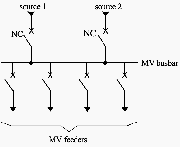
Go back to Power Supply Modes ↑
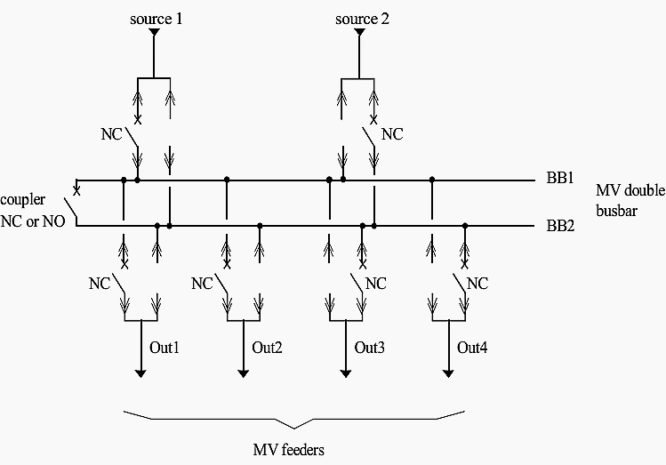
III – 2 bus sections with coupler, 2 supply sources
Operation Each source feeds one bus section. The bus coupler circuit-breaker can be kept closed or open. If one source is lost, the coupler circuit-breaker is closed and the other source feeds both bus sections.
If a fault occurs in a bus section (or maintenance is carried out on it), only one part of the outgoing feeders is no longer fed.

Go back to Power Supply Modes ↑
IV – 1 busbar with no coupler, 3 supply sources
Operation The power supply is normally provided by two parallel-connected sources. If one of these two sources is lost, the third provides a back-up supply. If a fault occurs on the busbar (or maintenance is carried out on it), the outgoing feeders are no longer fed.
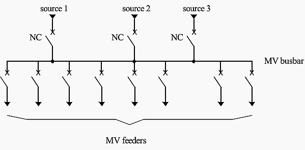
Go back to Power Supply Modes ↑
V – 3 bus sections with couplers, 3 supply sources
Operation Both bus coupler circuit-breakers can be kept open or closed. Each supply source feeds its own bus section. If one source is lost, the associated coupler circuit-breaker is closed, one source feeds two bus sections and the other feeds one bus section.
If a fault occurs on one bus section (or if maintenance is carried out on it), only one part of the outgoing feeders is no longer fed.
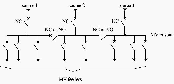
Go back to Power Supply Modes ↑
VI – 2 busbars, 2 connections per outgoing feeder, 2 supply sources
Operation Each outgoing feeder can be fed by one or other of the busbars, depending on the state of the isolators which are associated with it, and only one isolator per outgoing feeder must be closed.
If one source is lost, the other source takes over the total power supply. If a fault occurs on a busbar (or maintenance is carried out on it), the coupler circuit-breaker is opened and the other busbar feeds all the outgoing feeders.
Go back to Power Supply Modes ↑
VII – 2 interconnected double busbars
Operation This arrangement is almost identical to the previous one (two busbars, two connections per feeder, two supply sources). The splitting up of the double busbars into two switchboards with coupler (via CB1 and CB2) provides greater operating flexibility.
Each busbar feeds a smaller number of feeders during normal operation.

Go back to Power Supply Modes ↑
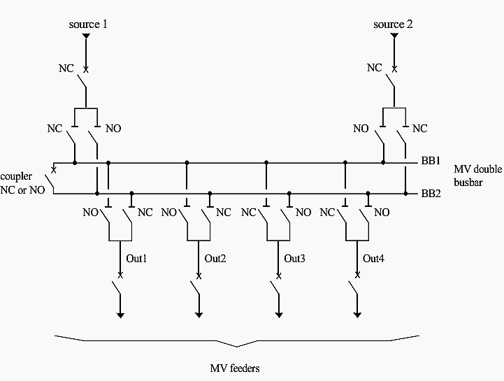
VIII – “Duplex” distribution system
Operation Each source can feed one or other of the busbars via its two drawout circuit-breaker cubicles. For economic reasons, there is only one circuit-breaker for the two drawout cubicles, which are installed alongside one another. It is thus easy to move the circuit-breaker from one cubicle to the other.
Thus, if source 1 is to feed busbar BB2, the circuit-breaker is moved into the other cubicle associated with source 1.
The same principle is used for the outgoing feeders. Thus, there are two drawout cubicles and only one circuit-breaker associated with each outgoing feeder. Each outgoing feeder can be fed by one or other of the busbars depending on where the circuit-breaker is positioned.
If one source is lost, the other source provides the total power supply. If maintenance is carried out on one of the busbars, the coupler circuit-breaker is opened and each circuit-breaker is placed on the busbar in service, so that all the outgoing feeders are fed. If a fault occurs on a busbar, it is put out of service.
Go back to Power Supply Modes ↑
Reference // Protection of Electrical Network – Christophe Prévé
Related electrical guides & articles


Edvard Csanyi
Hi, I'm an electrical engineer, programmer and founder of EEP - Electrical Engineering Portal. I worked twelve years at Schneider Electric in the position of technical support for low- and medium-voltage projects and the design of busbar trunking systems.I'm highly specialized in the design of LV/MV switchgear and low-voltage, high-power busbar trunking (<6300A) in substations, commercial buildings and industry facilities. I'm also a professional in AutoCAD programming.
Profile: Edvard Csanyi

can you please explain Scheme IV how it works? how to close the other source like from a transformer? what are the special arrangement?
The single bus bar system is always good for operation as well as for maintenance part. While doing maintenance, option of having UPS to give lighting circuit is better. Even in duplex busbar system, if the design is not done proper, it may be difficult to make work or maintenance while other source is on. So basic system is better
SOLAR SYSTEM SYNCHRONIZATION NATIONAL GRID NETWORKS DISTRIBUTION
can you kindly mention the total cost involvement of 132/11kV, 132/22kV and 132/33kV substations of same capacity? required capacities are 32MVA, 60MVA & 90MVA
transformer arrangement is 16MVAx2, 30MVAx2 and 45MVa x 2
12Nos outgoing bays are proposed.
The drawing 3 is the best, its very easy for any intervention, maintenance or any other probleme, but you must the both source egal, it means source1=source2, that mean they can work in parallely (same voltage, same frequance, same dephasage). So if you have a probleme in one line the seconde can take role. And the coupler will be closed.
please recheck schematic VI , i think something wrong about out1,2,3and 4 . must change the positions of NO. & NC. so that it will work properly as described .
thanks
Dear Friends i want to know the maximum make and brake of 5kvar shunt capacitor.
This refers to your article “8 schemes to supply MV switchboards. In the “Duplex distribution system” scheme, would it not be simpler to go for a 2 position switch instead of an empty cubicle. Drawing out a breaker & then inserting it is tedious process. Instead one can have switch to direct the power in the desired direction.
Thanks
The last techcical articles published are very poor and they add nothing to experienced engineers.
The topics covered are general, week and they don’t go deep into the matters.
Manuel, I agree partially with you. Article is not poor, but it’s general and presents basic solutions to connect your MV switchboard to network. I agree, expirienced engineer won’t learn much from this, but this one as every other article is not intended to be only for one side.
However, future articles in this subject will go little more deeper :)