Ground loops and signal noise
General recommendation is to properly design and implement the facility’s grounding system to avoid unwanted involvement of ground loops with the operation of the equipment. This kind of approach can also eliminate the need to consider equipment modifications and to engage in costly diagnostic efforts since most trouble involving common-mode noise is avoided in the signal circuits.
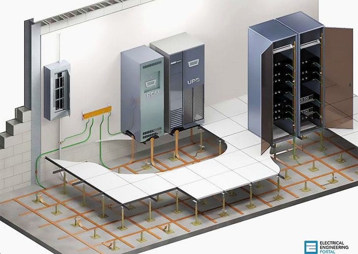
It is generally not possible in complex systems with interconnected data and signal conductors to avoid all ground loops.
Some eight tips that may be used to avoid the detrimental effects of such ground loops include:
Tip #1
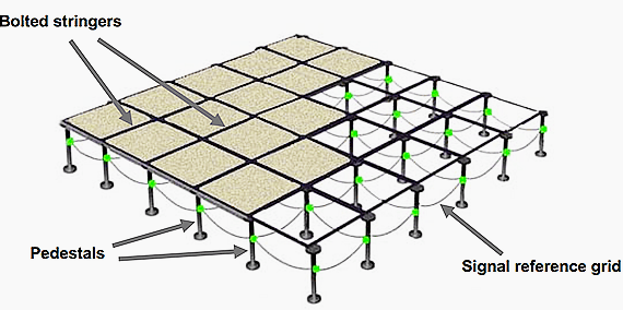
Where possible, cluster the interconnected electronic equipment into an area that is served by a single signal reference grid (SRG). If the interconnected equipment is located in separate, but adjacent rooms, then a common signal reference grid should serve all the rooms.

Tip #2
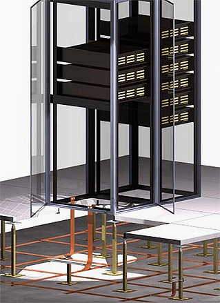
Effectively bond each frame/enclosure of the interconnected equipment to the SRG. In this way, the SRG acts like a uniformly shared ground reference that maintains a usefully low impedance over a very broad range of frequency. Typically, from dc to several tens of MHz, for example.

Tip #3 Where a work area exists and its PC is connected to a network, keep all of the work area’s equipment (e.g., CPU, monitor, printer, external modem, etc.) closely clustered and powered by a work area dedicated branch circuit. If it is required to use more than one branch circuit for the work area’s power, be sure that both are powered from the same panelboard.
Avoid connecting any other equipment to the branch circuit(s) used by the work area’s equipment.
Tip #4 Use fiber optical paths for data circuits. The best, but also the most expensive solution is to use fiber optical cables for all data circuits since there can be no ground loops with these kinds of circuits (or surge current problems).
However, due to increased initial cost and added complexity, the use of fiber optic cable circuits is usually (and unfortunately) viewed as a last resort. Instead, it should be viewed as an important first strategy that avoids problems that may ultimately cost more to resolve.
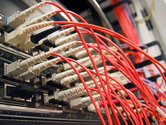

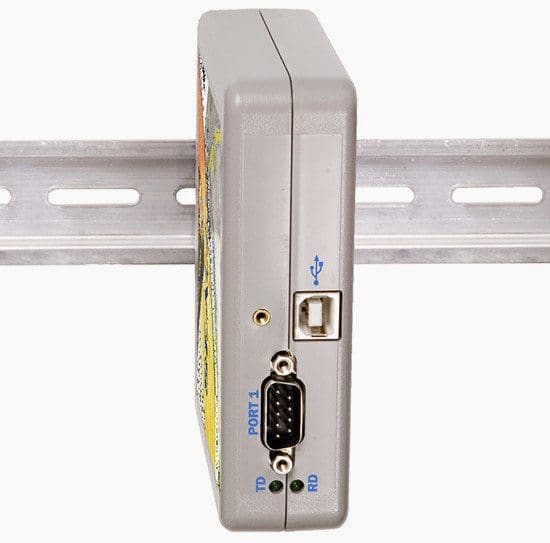
Tip #5 Use opto-isolators which can provide several kV of isolation for the data path that they are used on. These are available as add-on data transmission protocol converters for most popular forms of data circuits. This is a very useful retrofit option for data circuits being affected by surges and ground loops.
Tip #6 Other forms of protocol converters can be applied to standard forms of signal circuits to make them less susceptible to common-mode noise on grounding conductors associated with the signal path. For example, a conversion from RS-232 to RS-422 or RS-485, etc. should be considered in especially noisy environments.

Tip #7 Improve the shielding provided for the data signal cables. Place the cables into well and frequently grounded metal conduits or similar raceways.
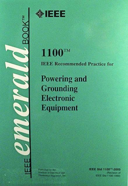
Tip #8 Follow the recommendations for installing signal cables in IEEE Std. 1100, Recommended Practice for Powering and Grounding Sensitive Electronic Equipment (e.g., the Emerald Book).

Equipment interconnected by data signal cables and located on different floors or that is widely separated in a building, may not be able to effectively use some or all of the above solutions, except those involving optical isolation and certain of the protocol conversion techniques. This occurs since the terminating equipment for the signal cables is likely to be powered from different branch circuits, panelboards, and even separately derived AC systems.
Therefore, the associated equipment ground references are likely to be at different potential at least some of the time.
Table // Ground noise susceptibility classes of different data cable types
| Total immunity | High immunity | Partial immunity | Low immunity |
| Fiber-optic Wireless | Ethernet | Modbus RS-485 SCSI | Parallel ports RS-232 ports Proprietery backplane Video cables |
While the best solution to the above situation involves either fiber optic or opto-isolation techniques, it is often possible to achieve good performance by providing each of the separate locations with an SRG, and then interconnecting the SRGs with widely spaced apart and multiple grounding/bonding conductors, solid-bottom metal cable trays, wireways, or conduits containing the data signal cables.
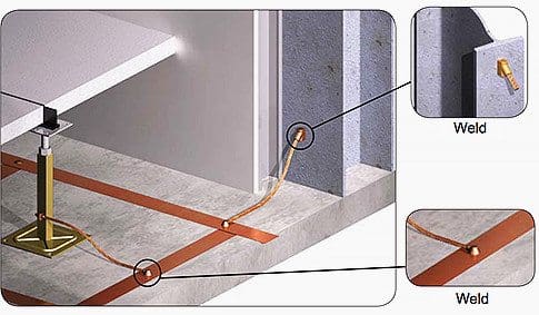

An example of using widely spaced grounding/bonding conductors to interconnect two SRG areas is when there is structural building steel available and when it can be used in this role. Since structural steel columns are installed on standard spacings in a given building, these columns can typically be used for the purpose. Wide spacing is necessary since the conductors involved are inductors and the mutual inductance between such conductors that are not widely spaced, is quite high.
Also, each of the above separated equipment areas containing SRGs should be AC powered from a locally installed and SRG referenced isolation transformer as opposed to them being powered from panelboards and feeders from some remotely located power source.
Finally, since separated areas in a building are subject to large potential differences due to lightning discharge currents and some forms of ac system ground faults, the ends of the signal cables should always be equipped with surge protection devices (SPDs).
References //
- Practical Guide to Electrical Grounding by W. Keith Switzer, Senior Staff Engineer
- Use of the Signal Reference Grid in Data Centers by Neil Rasmussen from APC




Thank you the above information helped clairify some gronding /bonding issues I was having.
You’re welcome, Allen!