
Estimated Study Time: 22 minutes
Electrical Grounding Techniques
Grounding and bonding are the basis upon which safety and power quality are built. The grounding system provides a low-impedance path for fault current and limits the voltage rise on the normally non-current-carrying metallic components of the electrical distribution system.

During fault conditions, low impedance results in high fault current flow, causing overcurrent protective devices to operate, clearing the fault quickly and safely. The grounding system also allows transients such as lightning to be safely diverted to earth.
Bonding is the intentional joining of normally non-current-carrying metallic components to form an electrically conductive path. This helps ensure that these metallic components are at the same potential, limiting potentially dangerous voltage differences.
Careful consideration should be given to installing a grounding system that exceeds the minimum NEC requirements for improved safety and power quality.
Recommended Techniques for Grounding:
- Equipment Grounding Conductors
- Isolated Grounding System
- Branch–Circuit Grounding
- Ground Resistance
- Ground Rods
- Ground Ring
- Grounding Electrode System
- Lightning Protection System
- Surge Protection Devices (SPD) (formerly called TVSS)
1. Equipment Grounding Conductors
The IEEE Emerald Book recommends the use of equipment-grounding conductors in all circuits, not relying on a raceway system alone for equipment grounding. Use equipment grounding conductors sized equal to the phase conductors to decrease circuit impedance and improve the clearing time of overcurrent protective devices.
Bond all metal enclosures, raceways, boxes, and equipment grounding conductors into one electrically continuous system. Consider the installation of an equipment grounding conductor of the wire type as a supplement to a conduit-only equipment grounding conductor for especially sensitive equipment.
The minimum size the equipment grounding conductor for safety is provided in NEC 250.122, but a full-size grounding conductor is recommended for power quality considerations.
Many small household appliances have a double-insulation system to help avoid shock hazard, in which case the equipment grounding conductor is not needed. Most heavy-duty appliances, tools, and equipment, whether of being cord-connected or hard-wired, necessitate an equipment grounding provision. These devices must be connected to an equipment grounding conductor or a grounded, three-prong receptacle.
Figure 1 – An example of an equipment grounding conductor

2. Isolated Grounding System
As permitted by NEC 250.146(D) and NEC 408.40 Exception, consider installing an isolated grounding system to provide a clean signal reference for the proper operation of sensitive electronic equipment.
Isolated grounding is a technique that attempts to reduce the chances of “noise” entering the sensitive equipment through the equipment grounding conductor. The grounding pin is not electrically connected to the device yoke, and, so, not connected to the metallic outlet box. It is therefore “isolated” from the green wire ground.
A separate conductor, green with a yellow stripe, is run to the panelboard with the rest of the circuit conductors, but it is usually not connected to the metallic enclosure. Instead it is insulated from the enclosure, and run all the way through to the ground bus of the service equipment or the ground connection of a separately derived system. Isolated grounding systems sometimes eliminate ground loop circulating currents.
Note that the NEC prefers the term isolated ground, while the IEEE prefers the term insulated ground.
Figure 2 – Isolated grounding system for branch circuits

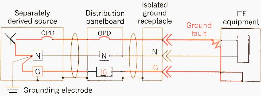
Isolated-Ground Wiring and Ground-Fault Current
It is equally crucial that the isolated ground wire establishes an adequate ground-fault pathway from the connected equipment to the power source. In the event of a ground fault at the load equipment, the IG grounding system would serve as a reliable ground path, as illustrated in Figure 3.
The IG conductor is permanent and continuous, possesses substantial current capacity—since it is sized according to NEC standards—and features a sufficiently low impedance path to enable the overcurrent protection device to clear the ground fault.
Figure 3 – Illustration of ground-fault pathway in an isolated-ground wiring configuration
Merits of Isolated-Ground Wiring Methods
Warren Lewis, a genuine innovator in power quality and grounding technology, once remarked, “isolated ground wiring, when correctly executed, serves as a significant power quality enhancement tool that may occasionally improve noise conditions, may have no effect, and at times can worsen the situation”. The key lies in identifying which time corresponds to which.
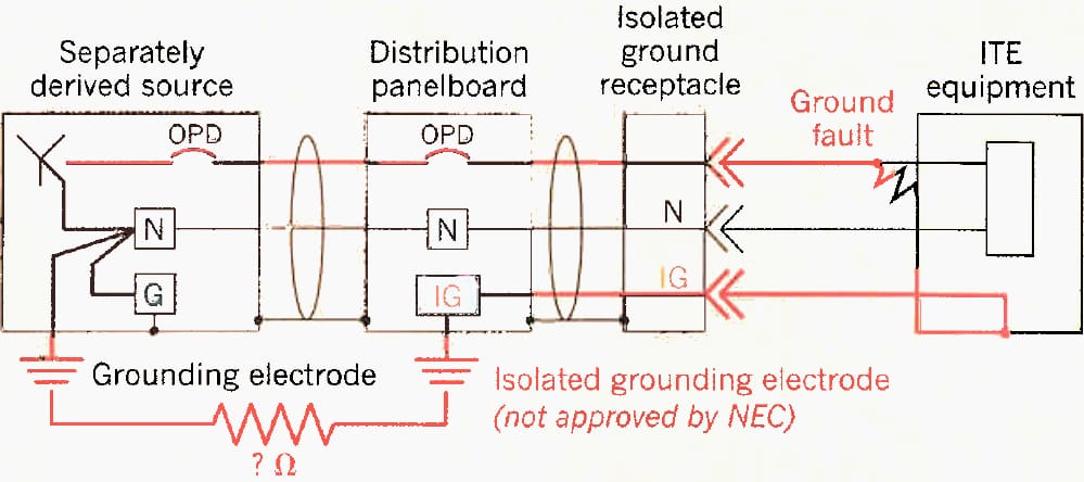
Electronics engineers frequently hesitate to properly apply isolated ground wiring, as seen in Figure 4, due to the absence of isolation for the sensitive electronic equipment ground path. A common remark is, “What benefit does it provide when the insulated ground is linked to the ‘dirty’ AC power ground, as mandated for safety?”
The evident response is that the conduit and metal enclosure system give EMI/RFI shielding for the power and isolated-ground conductors housed within it. However, that constitutes merely a portion of the advantages of isolated ground wiring.
Figure 4 – Isolated, dedicated grounds do not provide an effective ground-fault path
A practical advantage is that isolated ground wiring regulates the grounding connections of sensitive electronic equipment to mitigate issues related to stray ground currents. Refer to the example depicted in Figure 5, illustrating a typical (non-isolated ground) grounding configuration.
Stray ground currents passing the grounding system induce changes in ground potentials across the system.
These currents are a fundamental component of nearly all power systems and occur under various conditions, the majority of which are highly dynamic rather than steady-state.
In the case depicted in Figure 5, any ground current is going to raise the ground potential of the panelboard enclosure in relation to the power ground reference at the neutral-to-ground bonding point. In the usual grounding arrangement, the equipment ground reference of the computer system will increase in relation to the power ground, as the ground terminal at the panelboard is linked to the enclosure, which alters with variations in the enclosure’s ground potential.
Figure 5 – With typical ground arrangements, stray ground currents affect the sensitive load’s ground reference
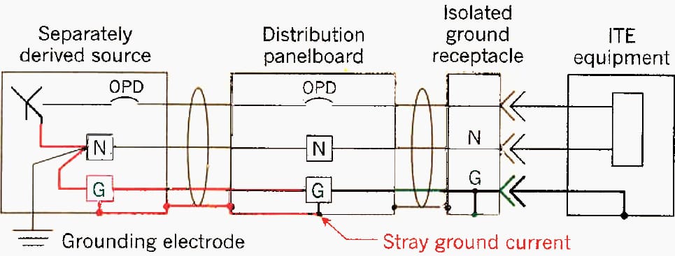
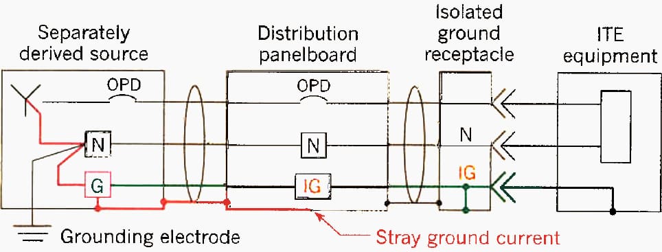
Figure 6 illustrates an alternative isolated ground schematics in which the equipment ground reference for the sensitive load is isolated from the metal conduit and enclosure grounding system. Stray ground currents passing the conduit and enclosure system utilize ground potential changes restricted to the grounding system of the conduit and enclosure.
The stray ground currents cannot pass through the isolated grounding wiring, hence not disturbing the ground reference of sensitive electronic equipment.
Figure 6 – With insulated-ground wiring arrangement, stray ground currents do not affect the sensitive load’s ground reference
Demerits of insulated ground wiring methods
Having outlined the prospective merits of isolated ground wiring methods, we shall now examine the possible drawbacks, one of which is to induced currents from the power wires. Think about how the ground (or isolated-ground) conductor is positioned in relation to the raceway’s power conductors.
Figure 7 illustrates the cross-section of two potential arrangements. In most electrical raceways within buildings, the placement of the ground conductor is, at best, arbitrary in relation to the power conductors, as several individual wires are typically employed instead of a manufactured cable that maintains a controlled relative positioning of the conductors.
When the ground conductor is not symmetrically positioned between the power conductors, the magnetic fields generated by the currents in the power conductors will be unbalanced in the ground conductor. The alternating magnetic field will generate current in the ground conductor if it is part of a complete circuit for current flow (ground loop).
In interconnected systems, where multiple load devices are linked via data, communication, or control cables, the implementation of isolated-ground wiring could worsen the issue of induced current.
As depicted in Figure 7 below, and ideal arrangement is where the ground conductor is equidistant from power conductors (left). However, in reality, the ground conductor is often not equidistant from the power conductors.
Figure 7 – Ground conductor position relative to the power conductors inside a conduit
3. Branch-Circuit Grounding
Replace branch circuits that do not contain an equipment ground with branch circuits with an equipment ground. Sensitive electronic equipment, such as computers and computer-controlled equipment, require the reference to ground provided by an equipment grounding conductor for proper operation and for protection from static electricity and power surges.
Surge Protection Devices (SPDs) must have connection to an equipment grounding conductor.
Useful Tool (XLSX) – Selection Of MCCB, ELCB For Main-Branch Circuit
Selection Of MCCB, ELCB For Main-Branch Circuit (MS Excel Spreadsheet)
4. Ground Resistance
Measure the resistance of the grounding electrode system to ground.
Take reasonable measures to ensure that the resistance to ground is 25 ohms or less for typical loads. In many industrial cases, particularly where electronic loads are present, there are requirements which need values as low as 5 ohms or less many times as low as 1 ohm.

For these special cases, establish a maintenance program for sensitive electronic loads to measure ground resistance semi-annually, initially, using a ground resistance meter. Ground resistance should be measured at least annually thereafter.
When conducting these measurements, appropriate safety precautions should be taken to reduce the risk of electrical shock.
Record the results for future reference. Investigate significant changes in ground resistance measurements compared with historical data, and correct deficiencies with the grounding system. Consult an electrical design professional for recommendations to reduce ground resistance where required.
An inadequate grounding system may expose us to electric shock risks, instrumentation measurement mistakes, harmonic distortion, power factor concerns, and various other complications. If fault currents lack a designated path to the earth via a properly engineered and maintained grounding system, they will seek other paths, potentially involving individuals.
Further Reading – What Is a Good Ground Resistance Value?
5. Ground Rods
The NEC permits ground rods to be spaced as little as 6 feet apart, but spheres-of-influence of the rods verlar.
Recommended practice is to space multiple ground rods a minimum of twice the length of the rod apart. Install deep-driven or chemically-enhanced ground rods in mountainous or rocky terrain, and where soil conditions are poor. Detailed design of grounding systems are beyond the scope of this document.
As a Code minimum, a single rod, pipe, or plate electrode is regarded as sufficient if it has a resistance to ground less than or equal to 25 ohms; otherwise, a supplemental electrode must be provided at a distance of at least six feet and must be bonded to the first electrode. This minimum criterion is deemed poor practice.
The Code, for example, is not requesting that a specified resistance be reached. Many electrical applications specify a resistance to ground of 2 ohms or less.
Grounding electrode conductors are normally connected to electrodes using exothermic welding, approved lugs, approved pressure connectors, approved clamps, or other approved methods, as outlined in NEC 250.70. If the connection is to be buried or encased in concrete, the listing must specify this condition. Copper conductors are the optimal selection for usage in concrete, direct earth contact, or exposure to environmental conditions.
This is not applicable to Copper-clad or Aluminum conductors.

6. Ground Ring
In some cases, it may be advisable to install a copper ground ring, supplemented by driven ground rods, for new commercial and industrial construction in addition to metal water piping, structural building steel, and concrete-encased electrodes, as required by Code.
Grounding rings provide a convenient place to bond multiple electrodes of a grounding system, such as multiple Ufer grounds, lightning down-conductors, multiple vertical electrodes, etc.
Install ground rings completely around buildings and structures and below the frost line in a trench offset a few feet from the footprint of the building or structure. Where low, ground impedance is essential, supplement the ground ring with driven ground rods in a triplex configuration at each corner of the building or structure, and at the mid-point of each side.
This earth electrode material is resistant to corrosion and does not necessitate labor-intensive and costly reconstruction efforts for the earth-termination system, such as the removal of paving stones, asphalt surfaces, or steps to install new grounding material.

The NEC-minimum conductor size for a ground ring is 2 AWG, but sizes as large as 500 kcmil are more frequently used. The larger the conductor and the longer the conductor, the more surface area is in contact with the earth, and the lower the resistance to earth.
7. Grounding Electrode System

Bond all grounding electrodes that are present, including metal underground water piping, structural building steel, concrete-encased electrodes, pipe and rod electrodes, plate electrodes, and the ground ring and all underground metal piping systems that cross the ground ring, to the grounding electrode system.
Bond the grounding electrodes of separate buildings in a campus environment together to create one grounding electrode system.
Bond all electrical systems, such as power, cable television, satellite television, and telephone systems, to the grounding electrode system. Bond outdoor metallic structures, such as antennas, radio towers, etc. to the grounding electrode system. Bond lightning protection down-conductors to the grounding electrode system.
Further Study – Earth electrode and earth loop impedance testing (Theory and applications)
Earth electrode and earth loop impedance testing (Theory and applications)
8. Lightning Protection System
Copper lightning protection systems may be superior to other metals in both corrosion and maintenance factors. NFPA 780 (Standard for the Installation of Lightning Protection Systems) should be considered as a minimum design standard.

A lightning protection system should only be connected to a high quality, low impedance, and robust grounding electrode system.
9. Surge Protection Devices (SPD) (formerly called TVSS)
The use of surge protection devices is highly recommended. Consult IEEE Standard 1100 (The Emerald Book) for design considerations. A surge protection system should only be connected to a high quality, low impedance, and robust grounding electrode system.

Generally, a surge protection device should not be installed downstream from an uninterruptible power supply (UPS). Consult manufacturers’ guidelines.
Reference // Recommended Practices for Designing and Installing Copper Building Wire Systems – Copper Development Association Inc.
Related electrical guides & articles


Edvard Csanyi
Hi, I'm an electrical engineer, programmer and founder of EEP - Electrical Engineering Portal. I worked twelve years at Schneider Electric in the position of technical support for low- and medium-voltage projects and the design of busbar trunking systems.I'm highly specialized in the design of LV/MV switchgear and low-voltage, high-power busbar trunking (<6300A) in substations, commercial buildings and industry facilities. I'm also a professional in AutoCAD programming.
Profile: Edvard Csanyi

what are your thoughts on the following. currently i have a data center, all racks, raised floor, ups and transformer are connected to a ground bus Wich is then connected to building steel. the data center is located on a 6th fl of a building. someone is suggesting we remove the main bonding jumper from the steel and instead run a ground cable down to first floor and connect to a ground rod. I have never seen this practice in my entire electrical career. is this allow? wouldnt this create an issue due to potential difference between the service ground rod and the ground rod that will be installed to the data center?
I wasn’t there
Do you have anything on voltage drop calculations for medium voltage ?
Really I’m thankful to you for this useful article.
Estimado Edvar,
muchas gracias por compartir tan buena y didáctica información, ojala pudiera considerar junto a los miembros que la componen, incluir mas literatura en español
Reciba Uds un gran saludo desde Chile.
Atentantamente,
Sergio Miranda.
Realy its very interesting and useful Site.For young and Old engineers.and
Hi Edward, your articles are always fantastic and educative. Need more on transmission and distribution power lines construction, operation and maintenance.
I am from a water utility company. A railway system is to be constructed between the locations of our steel pipelines. As per the comment of the Contractor of the railway system, they will be installing ground rods to every column of their railway system. These ground rod may affect the life span of our steel pipes.
What would be the minimum clearance between the ground rod and steel pipes to avoid this situation, if any? Or any method on how to protect our steel pipes life span?
I hope someone can answer my query.
I have a concern working on a grounding project — the grounding drawing are revision 4 okay — the problem is I notice a air termianal(Lightning protection on Rev 4) then I referenced to the Lightning Protection drawing and what shocked me is the Lightning Air Terminal is not located on this certain structure ( oh its LNG Plant ground up) then notice Revision 0 “on the Lightning Protection Drawing.
Correct me if I am wrong Lightning Protection goes to the ground right — then why was not the Lightning Protection Drawing up date as for as the Grounding — are does it matter.
I though that when never you up a revision on grounding and if the air terminals are to be tied in to the ground ring — should there a revision on the Lightning Protection also.
Please correct me if I am wrong – thank you
I always dislike AC power and wiring system. I have some experience with D.C. And AC. That’s all I have to comment.
Powerlines are running parallel to Buried Cross Country Coated Pipelines and are experiencing effect of aC induce votlage interference. We are installing copper grounding conductors of 25 sq mm cross section in carborneous coke backfill upto 150m long to get grounding resistance below 1 Ohms depending upon soil resistivity and connecting the two ends of copper grounding conductor ring to a cross country buried pipelines through a polarization cell to ground the buried coated pipeline to mitigate the effects of induce AC voltage on buried coated pipeline. After few months of installation we have found that the grounding copper conductor has oxidized and turning into green powder and copper ring got into various pieces. Please advice if copper is reacting with carbon backfill or high current discharge through grounding system is oxidizing the copper grounding ring.
that my job and i have more idea in this thank u
Excellent article!
So IG goes from isolated receptacle ground without bonding to anything back to service panel and connects to its own insulated, non bonded ground bus and the to independante grounding rod?
SG is ground for all the mechanal bonds at receptacle, conduits, structure, neutral-ground and es to its separate ground rod so that both IG and SG never physically, mecanically bond?
Correct?
As always, Edvard, another informative article!
Am I correct to understand that for IG the ground pin is totally isolated at the receptacle and that conductor runs directly to the service panel?
The SG conductor bonds/connects all metal parts/strutures and electrically connects at the service panel.
That at the service panel there would be two grounding buses:
a. One that bonds nuetral-ground-metal parts, etc and the SG conductor then will go to a grounding electrode.
b. The other would be completely be isolated from metal parts, the grounded neutral and will bond the IG to its independant grouding electrodes.
Therefore, there would not be a physical, a mechanical bond of these two grounds, correct?
Would such cabling of L-N-G-IG conducters be applicable or necessary in an office, bank, or school?
I see the sense in hospital and some industrial applications.
Thanks
Señor Edvar, no soy Ingeniero, en mi país existe también un titulo menor y es de Tecnologo Eléctrico, desde hace un par de semanas que encontré su blog sigo y estudio de cerca sus aportes son muy bien explicados ademas de ajustados a la experiencia en campo, gracias por sus aportes son claros y me han despejado dudas.
Saludos desde Sur America
I will read all the articles of Edvard hereon.
Thanks for the insight.
Edvard,
You are great ! I like all your EE articles issued. I am certainly sure that these helps engineers, professors,students, practitioner, EE project management team in the world .
I am an experienced electrical engineer too and there are informative articles i read and even down load them for references.
Sir Edvard appreciate If you could issue ieee standard 1100 ( the emerald book ) as well I think this would give more information to all ee practitioners.
Man you are great! and more power for you. You help many people…
Thanks a lot …
hi
I am electrical power eng.
I like your work and am intresting to have your technical subjects please.
Please specify whether any special earthing is required for tuned filters and active filters in harmonic mitigation system. Can this earthing be connected to common grid earthing?
Picture 4 could you have used the term fall of potential & talked about how you use Ohm law to teach the reason you use this way of of testing younger generation only learn what us older ones make them aware of just my thought kohli
Mr. Kohli, if he used the term fall of potential would you think that everyone else will know meaning of that term. I think he explained it in a simple way so anyone can understand and that is a start. The reader will do his own research later on. This is still an informative and helpful site.
In the picture with # 5 you use a green with yellow that is O K But why did you use a picture with a coiled conductor if by chance the voltage applied
to this conductor was above , 600v or less than the current could be of a maganatude that some counter E M F could cause the voltage to rise on the other part of the system & not let the earthing / grounding do what it is to do just my thought B kohli at [email protected]
in other subject (bonding earthing and grounding) you explain the difference bet. grounding and earthing.
grounding is related to powr system common zero point which can be neutral in star connection.
but earthing is for dead parts connection to the earth
here you use term grounding for lightening system which is not power system or neutral point.
thanks in advanc
hamdy anwar
Some of earthing Activity give us the standard value for each earthing resistance standard value,
1- Medium voltage switchgear.
2- power transformer.
3- light current equipments.
and there is other values.
Abdelkawy Almasry.