
UHV GIS structure
Ultra-high voltage (UHV) AC gas insulated switchgear (GIS) can correctly work only if all its internal components are properly assembled and the metal enclosure is filled with SF6 gas at the required density. That’s obligatory. As in the lower HV voltage levels, the density of filled SF6 gas in UHV switchgears depends on the required internal arc extinction and insulation performance.
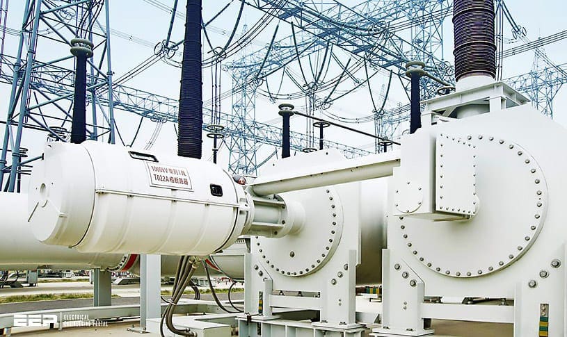 Ultra-high voltage (UHV) AC gas insulated switchgear (GIS) for 1000kV and above (on photo: Jingmen substation, China; credit: ABB)
Structurally, GIS mainly comprises the current-carrying part (or internal conductor), insulation structure, enclosure, operating mechanism, gas system, grounding system, auxiliary circuit, and components.
In GIS, some components have their own separate gas chambers and some components are connected together and share the same gas chamber. Different chambers may be filled with gas of different densities. The conductive parts inside the metal enclosure are supported on the latter using cast epoxy resin insulators and different chambers are connected electrically with metal fittings.
The connecting flanges between the enclosures must be precisely machined and high-pressure gas should thus tightly sealed within the enclosures with the aid of corrosion-resistant rubber O-rings. In addition, the enclosures are generally provided with relief valves or rupture discs.
UHV GIS can be classified into two types:
- Three-phase non-segregated type and
- Phase-segregated type).
For three-phase non-segregated GIS, the three phases are housed within the same enclosure and spaced apart using insulating supports or plates. This structure can reduce both the metal enclosure material consumption and land occupation.
Figure 1 shows the schematic diagram of the internal structure of three-phase non-segregated GIS.
Where:
- Bus
- Disconnector
- Earthing switch
- Circuit breaker
- Current transformer
- Voltage transformer
- Cable terminal
For phase-segregated GIS, the apparatus for individual phases is installed in separate metal enclosures so that the main circuit of each phase has its separate enclosure. This will create a coaxial cylinder electrode system. In this case, the electric field is evenly distributed, the GIS structure is simple, and the insulation problem can be easily addressed.
As a result, no phase-to-phase short-circuit fault will occur. Therefore, GIS that are 330 kV or higher usually use this structure.
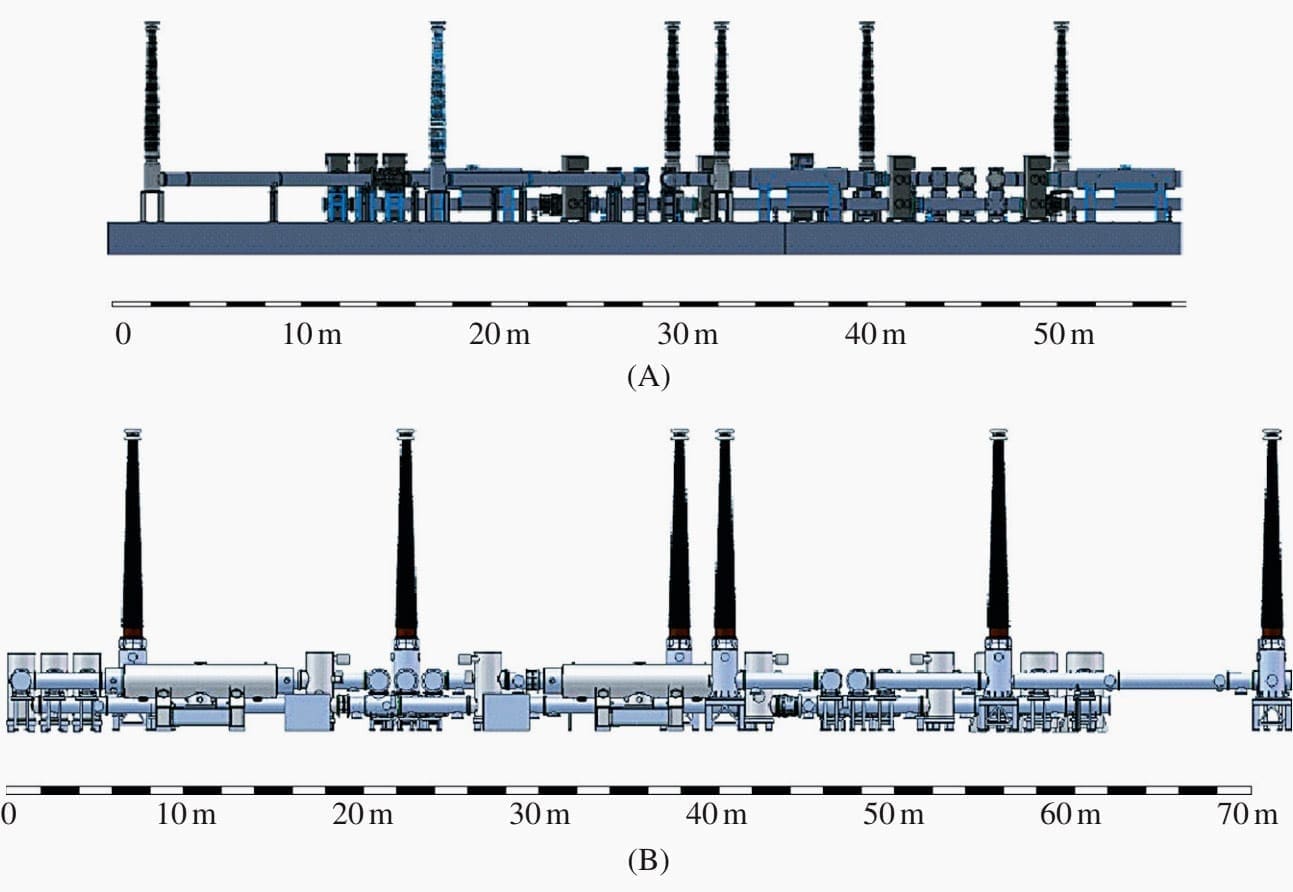
Figure 2 shows the dimensions of 750-kV GIS and 1000-kV GIS for comparison.
GIS has the following advantages over air-insulated switchgear (AIS):
- Its land occupation is only approximately 40% that of the AIS, contributing to a large amount of saved land;
- All live parts are enclosed within a metal enclosure and the environmental electromagnetic pollution due to HV can thus be avoided;
- Personal injuries and deaths due to electric shock can be avoided;
- The equipment overhaul interval can be prolonged and the equipment is generally not required to be disassembled and repaired for 10-20 years; and
- The equipment insulation performance is not affected by atmospheric conditions, the seismic resistance performance is improved, and the operational reliability is enhanced.
GIS is more costly than conventional electrical equipment.
Related electrical guides & articles


Edvard Csanyi
Hi, I'm an electrical engineer, programmer and founder of EEP - Electrical Engineering Portal. I worked twelve years at Schneider Electric in the position of technical support for low- and medium-voltage projects and the design of busbar trunking systems.I'm highly specialized in the design of LV/MV switchgear and low-voltage, high-power busbar trunking (<6300A) in substations, commercial buildings and industry facilities. I'm also a professional in AutoCAD programming.
Profile: Edvard Csanyi
