
Estimated Study Time: 62 minutes
Switchyard Equipment in a Nutshell
This article provides details on the various types of switchyard equipment, including power transformers, circuit breakers, disconnectors, and more. The technical specifications (or tender specifications) for each individual piece of equipment are laid forth. The related course, guide or article for each switchyard equipment for further study is suggested.
 Technical specification of switchyard equipment in a nutshell (how-to guidelines and advice)
The network engineering studies are a pre-requisite for setting these specifications, as the basic power system parameters (i.e., P, Q, V, I) are determined in such studies.
Load flow study for instance sets the rated power limit for the equipment whilst the short circuit study determines the tolerance of these equipment types for abnormal cases. The bottom line is that these engineering studies need to be finalized before settling the equipment specifications.
Furthermore, more elaborate and specific parameters are finalized for each equipment type that suits its functionality. CBs, for example, is one of the complex equipment that needs close scrutiny to avoid any later maloperation. Other switchyard equipment types are discussed in terms of functionality, main concerns, related standards, basic parameters, and testing lists.
However, due to complexity of subject, this article only scratches the surface of the switchyard design.
- Introduction to Switchyard
- Power System Studies
- Switchyard Equipment Specifications
1. Introduction to Switchyard
The switchyard is a switching station that serves as the primary connection between the power generation facility and the transmission network. A switchyard is a junction that carries the power that has been generated to its destination. It also plays a significant role in the system’s overall security and has the ability to control reactive power devices, which are known to play a significant part in the power quality.
It is mostly composed of switches, power circuit breakers (CBs), and other auxiliary equipment. Its primary function is to collect electricity from the generators located at the power plant. After that, the power will be delivered to the transmission lines located at a load point.
In order to insulate the various components of the substation from one another and to ensure that the charge is properly grounded, they make use of air.
Figure 1 – Typical general layouts of a switchyard feeder

Copper grounding is performed on the majority of the equipment and in the ground throughout the majority of the substation in order to protect the system and ensure that it is correctly grounded. On the other hand, the phase-to-phase and phase-to-ground insulation in the GIS is created with a superior dielectric gas such as SF6, which is compressed to a modest level.
In situations with limited room, GIS is also utilized. The dynamic components of a GIS are shielded from the effects of air pollution. For example, a current transformer, switches, and circuit breakers (CBs) are encased in SF6 gas and housed within a grounded metal enclosure in this sort of switchyard.
The primary function of the switchyard, in its most fundamental sense, is to move the electricity that has been created to the location where it will be switched on and off by the associated equipment.
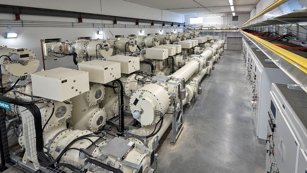
Figure 2 – Gas-Insulated switchgear installed in room
Switchgear is a collection of electrical disconnect switches, such as fuses or circuit breakers (CBs), that are used to control, protect, and isolate electrical equipment in the event that a fault situation occurs. The switching, protection, and control of an electrical circuit are the responsibilities of a switchgear, which is a type of electrical enclosure.
Having said that, a switchyard is in no way comparable to it. Switchgear may be a piece of equipment that is found in a switchyard, but the transmission of power that is generated in a power plant is done with the assistance of a switchyard, which acts as a junction where the power transmission takes place.
The switchyard can provide additional protection for the power plant as well as assistance with the transfer of electricity.
Figure 3 – Switchyard example

Go back to the Contents Table ↑
2. Power System Studies
For planning, designing, and running industrial and commercial power systems, engineering studies are needed to look at the performance, reliability, safety, and economics of existing and proposed systems. When planned and done right, studies are a cost-effective way to avoid surprises and choose the best equipment.
Studies are done during the design phase to find and fix any problems with the system before it is put into use. In systems that are already in place, the studies help find out why equipment breaks down or doesn’t work right and figure out how to fix things to make the system work better.
Power system analysis software such as load flow, short circuit, harmonic analysis, protective device coordination, and stability is available on a personal computer at a reasonable cost.
Go back to the Contents Table ↑
2.1. Load Flow Study
Load flow studies assess the voltage, current, active and reactive power, and power factor of a power system. Load flow studies are a great resource for system planning. A variety of operating processes, including contingency scenarios such as the loss of a generator, transmission line, transformer, or load, can be examined.
The results of a load flow study can also be used as a starting point for additional research such as short circuit and stability investigations.
Suggested Course – Power System Modeling and Stability Analysis Using ETAP
Power System Modeling and Stability Analysis Using ETAP – Beginner to Advance Level Course
Go back to the Contents Table ↑
2.2. Short Circuit Study
Short-circuit studies are performed to assess the amount of anticipated currents flowing throughout the power system at various time periods following the occurrence of a fault. After a defect, the size of the currents flowing through the power system vary with time until they achieve a steady-state condition.
This is attributable to the system’s properties and dynamics. The protective system is called upon at this period to detect, interrupt, and isolate these failures. The duty placed on this equipment is determined by the amount of the current, which is determined by the time from the onset of the fault.
Moreover, the equipment damage curves are assessed before finalizing their corresponding specifications. The grounding system design relies on the short circuit study as well. In high-voltage substations, it is extremely important to account for the voltage experienced during fault conditions since it might affect the insulation coordination and lightning arrestor applications.
Suggested Course – Power System Analysis: The Essentials of Load Flow and Short Circuits
Power System Analysis Course: The Essentials of Load Flow and Short Circuits
Go back to the Contents Table ↑
2.3. Stability Study
The capacity of a power system with two or more synchronous machines to continue operating after a system change is a measure of its stability. The stability problem can be divided into two types: steady-state and transient.
The ability of a power system to retain synchronism amongst machines within the system following relatively gradual load fluctuations is referred to as steady-state stability. The ability of a system to maintain synchronism under transitory situations is referred to as transient stability (i.e., faults, switching operations, etc).
Load-shedding methods and critical fault-clearing periods can be calculated in order to select the appropriate protective relay settings. These are most likely the most sophisticated studies performed on a power system. A simulation will comprise models of synchronous generators and associated controls (i.e., voltage regulators, excitation systems, and governors).
Motors, like static var compensators and protective relays, are sometimes represented by their dynamic characteristics.
Related electrical guides & articles


Salem Alshahrani
Electrical engineer (BEE & Meng). Specialized in substation design, especially in LV/MV switchgears and transformers. Passionate in power system planning, analysis, and stability studies.Profile: Salem Alshahrani
