
Estimated Study Time: 29 minutes
System Commissioning
No matter the approach, it is necessary that the testing engineers who will be responsible for commissioning the switchgear have a solid comprehension of the equipment that will be utilized and the various modes of operation that will be utilized. It is also extremely important to ensure that both the employees and the plant are safe while commissioning, and the best way to do this is through careful planning as well as the recording of both procedures and safety measures.
 Thumb rules, dos and don’ts in MV/HV switchgear testing and commissioning
Since there must not under any circumstances be a rush on the commissioning time, the planning for the project must take into consideration the possibility of delays occurring in the early stages of the project’s timeline.
Commissioning should also have a sufficient budget allocated to it. A common provision for commissioning is one percent to one and a half percent of the total cost of the electrical system.
1. Standards Covering Switchgear Testing
The following standards cover switchgear testing:
- IEC 62271-100: High voltage switchgear and control gear – HV alternating current circuit breakers
- IEC 62271-1: High-voltage switchgear and controlgear – Part 1: Common specifications for alternating current switchgear and
- IEC 62271-101: High-voltage switchgear and controlgear – Part 101: Synthetic testing
- IEC 62271-203: High voltage switchgear and control gear – Gas-insulated metal-enclosed switchgear for rated voltages of 72.5 kV and above
- IEC 60060: High voltage test techniques
- IEC 60480: Specifications for the re-use of sulphur hexafluoride (SF6) and its mixtures in electrical equipment
- controlgear
Go back to the Contents Table ↑
2. Switchgear Type tests
The following switchgear test are considered as type tests:
- Dielectric measurement.
- Temperature rise tests.
- Making and breaking tests.
- Mechanical endurance.
Let’s have a word about each test:
2.1 Dielectric Measurements
Is switchgear able to withstand the voltage stresses?
Dielectric measurements indicate that switchgear with a specific voltage rating can withstand the voltage stresses expected in service from switching operations or lightning surges. The switchgear is subjected to one-minute power frequency voltage withstand testing. A voltage greater than the rated voltage of the switchgear is used to validate proper clearances and insulation strength between phases, across open contacts, and between phase and earth.
The tests also examine the withstand capabilities of switchgear closing and opening resistors, GIS designs, and grading capacitors. When calculating the test voltage to be used, a suitable margin between the withstand voltage levels and transitory overvoltages that may occur during switching operations must be provided for.
Furthermore, the performance of asymmetric electrode morphologies at various high test voltage polarities must be examined.
Switchgear operating at high altitude, where the air density is lower, requires, for instance, larger switchgear clearances to be accounted for in designs. To account for the higher withstand voltage of air at sea level, the type test voltage is also raised.
Type testing should be carried out under the most unfavorable conditions, as the dielectric strength of SF6 fluctuates with density.
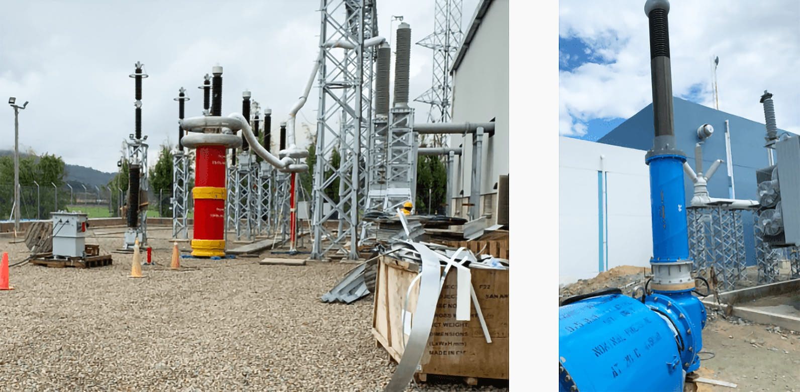
Figure 1 – Dielectric tests performed on GIS switchgear

Tests on outdoor gear can be carried out in either dry or wet environments, depending on the requirements of the product. As a technique of ensuring suitable insulator profiles and creepage distances, the wet conditions make an attempt to take into account the effects of water cascading down the switchgear porcelain insulators. This is done by taking into account the wet circumstances.
The performance of insulators in dirty or low-temperature ice circumstances also needs to be evaluated and is the subject of particular agreements between the client or his engineer and the switchgear or insulator makers.
A standard test consists of applying test voltages between each phase and earth in turn 15 times while the circuit breaker is closed and the remaining phases are earthed. Normally, a standard 1.2/50 s impulse voltage wave shape is used to simulate lightning strike conditions, and a 250/2500 s wave shape is used to simulate switching surges.
Additionally, test voltages are provided across each set of open circuit breaker contacts. This is done in addition to the previous step. If there are not more than two flashovers during any one series of 15 tests, then the overall test is regarded to have been successful. However, these discharges can only take place in self-restoring insulation (such as air, oil, or SF6 gas), therefore this requirement must be met.
In most cases, an inability to recover from a test failure caused by a breakdown of solid insulation is the outcome of the breakdown.
In the event that it is necessary, more investigations to verify this could be carried out.
Figure 2 – High-Voltage Testing and Partial Discharge Measurements in GIS-Air Connection GIS Bushing
The above GIS Test Transformers typically either use oil or SF6 as their insulating medium. Oil transformers have significantly higher power outputs and tuning ranges, however they cannot be connected directly to the GIS bus and must utilize external air connections. SF6 transformers with direct SF6 bus to the test object are the preferred method of connection for PD measurements.
When the switchgear is subjected to rated voltages higher than 300 kV, a bias test is carried out on it. The design of the circuit breaker is tested under the conditions of a lightning strike with the switchgear in the open position and the waveform peaks in the opposite polarity by applying a power frequency to one terminal of the circuit breaker and a lightning impulse to the other terminal. This is done so that the design can be validated under these conditions.
In most cases, partial discharge tests are not required to be performed as a component of a full circuit breaker assembly type examination. However, partial discharge testing is especially useful for switchgear systems that include components that have solid insulation.
The oscillograph traces might be used to make an effort at determining the voltage levels that were present at the beginning and end of the discharge. An examination of the traces enables a determination to be made as to whether the failure was caused by voids in the insulation, corona discharge, or some other factor.
During the testing of the power frequency overvoltage, another option is to determine the maximum discharge level, which is measured in picocoulombs.
Suggested Video – Voltage withstand test on a GIS 123 kV
Interference from electromagnetic fields can be caused by external discharges. Corona breakdown can be observed visually in a dimly lit laboratory, and the voltages at the moment of genesis and extinction can be measured. Radio noise levels that are the result of external discharges are measured in decibels (dB) above a reference level that is expressed in microvolts (μV).
According to IEC 62271, Table 1 outlines the lightning impulse and switching overvoltage levels that circuit breakers are rated for.
Table 1 – Circuit breaker rated lighting impulse & switching overvoltage levels (IEC 62271)
Note: Per unit maximum permissible switching overvoltage = peak value (kV peak) / {rated value (kV rms) × √2 /3}
Go back to the Contents Table ↑
2.2 Temperature Rise Tests
Can closed switchgear contacts handle higher temperature?
When the switchgear contacts are closed, the current that should be passing through them is the one that corresponds to the correct power frequency rating. In order to establish the continuous ultimate temperature rise at various temperature sensor positions on the switchgear, plots of temperature against time are recorded.
The many switchgear components each have their own unique set of standard permissible temperature rise limits.
Related electrical guides & articles


Edvard Csanyi
Hi, I'm an electrical engineer, programmer and founder of EEP - Electrical Engineering Portal. I worked twelve years at Schneider Electric in the position of technical support for low- and medium-voltage projects and the design of busbar trunking systems.I'm highly specialized in the design of LV/MV switchgear and low-voltage, high-power busbar trunking (<6300A) in substations, commercial buildings and industry facilities. I'm also a professional in AutoCAD programming.
Profile: Edvard Csanyi
