
Estimated Study Time: 31 minutes
Generator synchronization techniques
There are two main types of generator synchronization techniques: manual and automatic. The operator performs speed and voltage adjustments on the generator and issues the breaker closure command during a manual synchronization. Manual synchronization, in its purest form, is done by the operator without any external aid or constraints.
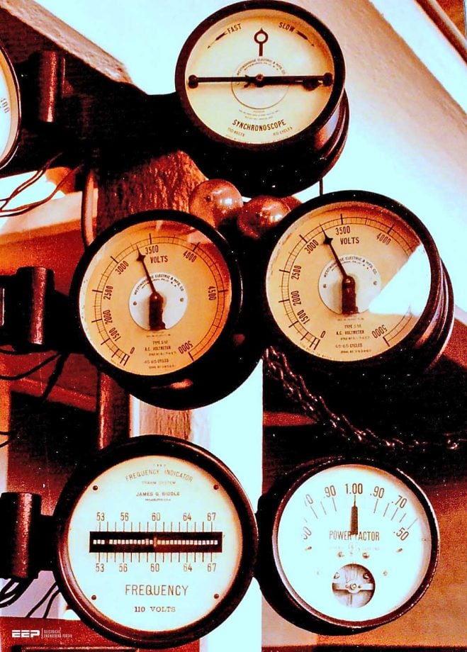 The art of synchronizing generator to the grid by adjusting the generator speed and voltage (on photo: Original gauges at the Pelzer Upper Hydro from 1920. The topmost gauge is used to synchronize the output of each generator with the others as they are individually brought on line. Despite the possibility of major damage if the generators were not synchronized properly, the operation was still done entirely by hand. The two middle gauges show the voltage output of each generator. With the exception of the original hydro operation, no other facility in the world generated power at 3.300 volts. The lower left gauge indicates the alternating current frequency of 60 hertz. The lower right gauge indicated power factor, which is essentially an indicator of efficiency.; credit: overWHAMmed via Flickr)
To avoid out-of-phase closures due to human mistake, preventive functions are currently used to monitor synchronization performed by hand. In the last two decades, both automated and manual synchronization techniques have incorporated more complex protective functions that can have their parameters adjusted by the user.
The first sixty years of the power industry relied on the expertise of a qualified operator to maintain synchronization. A catastrophic out-of-phase closure would not be trusted to an automatic system that could fail. Electrical and mechanical systems have become less tolerant of the rough synchronization of impatient or inattentive operators as generator sizes have grown and designs have become more efficient.
Manufacturers have been less flexible in their designs as evidenced by the strict constraints set on closing angle, voltage difference, and slip frequency.
Synchronization equipment in plants can be operated manually or automatically. The goal is to always employ the automatic system, and resort to the manual method only when necessary.
However, the way that is actually adopted depends on the philosophy of the plant in question and, in some situations, the level of annoyance with the automatic synchronization equipment.
- Manual Synchronizing
- Automatic Synchronizing
- Synchronism Check Relays (Device 25)
1. Manual Synchronizing
Since the early days of parallel generator operation, when a black lamp synchronizer was utilized, synchronizing equipment has gone a long way. Lights were wired across the open breaker’s like phases for this procedure. The system voltage and generator voltage were each measured using separate voltmeters.
The governor controls would be used initially to get the generator close to rated speed. Then he’d adjust the voltage regulator until the output from the generator was in line with the rest of the electrical grid. Then, the operator would keep an eye on the lights. The lights flickered at the slip frequency as the generator voltage rotated in relation to the system voltage.
If the generator and the system were 180 degrees out of phase with one another, the lamp would be brightest, and it would be turned off if the two voltages were perfectly in phase with one another. The light pulsations would then gradually decrease as the operator fine-tuned the generator speed.
This points to a frequency match between the system and the generator that is extremely near. When the lights went out, the operator knew the voltages were in sync and the phases were correct, so they closed the circuit breakers.
However, more secure synchronization techniques have been developed due to the possibility for harm from a major out-of-phase closure or shortened service life due to frequent harsh closures.
Current manual synchronizing tools are shown in Figure 1. Measuring the voltage on both sides of the synchronizing breaker is still necessary to ensure that the system and generator are operating at the same voltage. As shown in Figure 2 (see below), a synchroscope is now used to visually inspect the frequency and phase angle match between the two systems.
The scope’s frequency indicator will spin clockwise if the generator’s frequency is higher than the system’s. The generator will spin counterclockwise if its frequency is lower than the power grid’s.
Figure 1 – Manual synchronizing

The rotational velocity represents the frequency discordance (slip) between the two systems. The phase difference between the two voltages can be seen in real time by adjusting the scope’s position. The voltages are in phase when the clock is set at 12 o’clock. At the 2:00 location, the voltage difference between the two sources is 60 degrees, or 36×2/12.
Assume a generator manufacturer requires synchronization to occur within 10 degrees of the in-phase (zero degree) position with a slip of less than 0.067 hertz to get a feel for the process. The scope cannot rotate faster than around once every 15 seconds due to the slip limitation (1 rotation in 14.9 seconds; 1 over 0.067 seconds).
With a 10° angular limit, the operator must close the circuit breakers when the synchroscope indicator is 1/3 of the way between 12:00 and 11:00 (10/360 × 12 = 0.33).
When synchronizing completely manually, the operator sends an unattended close order to the breaker through the breaker control switch. This type of operator-only setup is almost extinct.
For transmission lines, much greater angular settings are required. Although the operator still has some say in the closing process, his ability to perform a wildly out-of-phase closure has been limited.
Figure 2 – Synchroscope

2. Automatic Synchronizing
As shown in Figure 3, automatic synchronizers don’t require any human involvement to close the breaker and synchronize the generator. The generator’s initial startup and initial acceleration are within the operator’s control. The voltage increases as the generator speed increases.
The generator frequency can be measured and synchronized by the automatic synchronizer between 70% and 80% of rated voltage.
A breaker closure signal may be generated depending on the type of synchronizer as soon as all parameters fall within the limits set forth. When all limitations are met, the anticipatory synchronizer will use real-time slip data and the breaker closing time to determine the close initiation angle required to generate a closure at the zero degree position.
Figure 3 – Automatic synchronizing

The synchronizer sends the close command at the calculated angle. Anticipatory synchronizers require some system slip to function. Modern synchronizers can work with slip as low as 0.0001 Hz. This corresponds to one synchroscope revolution every 2.8 hours.
This function accepts a little increase in slip in order to speed up breaker shutting. To ensure safe synchronization, automatic synchronizers offer a range of settable closing limit parameters. However, if the synchronizer fails, these constraints are meaningless.
Related electrical guides & articles


Edvard Csanyi
Hi, I'm an electrical engineer, programmer and founder of EEP - Electrical Engineering Portal. I worked twelve years at Schneider Electric in the position of technical support for low- and medium-voltage projects and the design of busbar trunking systems.I'm highly specialized in the design of LV/MV switchgear and low-voltage, high-power busbar trunking (<6300A) in substations, commercial buildings and industry facilities. I'm also a professional in AutoCAD programming.
Profile: Edvard Csanyi
