
Estimated Study Time: 33 minutes
Breaking Into the Interlocking Logic
As we delve deeper into this article, we will explore the various types of interlocking mechanisms used for Gas-Insulated Substation (GIS), their applications in substations, power plants, and electrical installations, as well as their significance in ensuring the sustained safety and functionality of these vital components of the power transmission infrastructure.
 Mastering Interlock Logic and Schemes for a Gas-Insulated Substation (132 kV GIS Example)
To start with the discussion, first let’s ask a few very important questions and try to give simple and straight-forward answers.
How to ensure proper operation of substation components? Well, let’s say that substations play a pivotal role in the seamless and safe transmission of electrical power. Ensuring the proper operation of various components within substations is of paramount importance to both personnel safety and the integrity of the entire electrical system.
To achieve this, substations are equipped with a comprehensive interlocking scheme, which is a critical safety measure in this high-voltage environment.
How to ensure sequential operation for safety? The primary purpose of interlocking within substations is to enforce a specific sequence of operations. This sequence ensures that all disconnectors, fixed earthing switches, or other interlocked devices, and, when necessary, circuit breakers, are operated in the correct order.
How to enhance personnel safety and system reliability? Beyond preventing operational errors, interlocking extends its reach into enhancing safety measures within substations. It goes beyond safeguarding against incorrect equipment operation. Interlocking systems are meticulously designed to limit access to specific areas, particularly where there is a potential for normal safety clearances to be compromised.
By restricting access to these high-risk zones, interlocking helps mitigate the chances of accidents and ensures that personnel remain safe while performing their duties in the substation.
How important is interlocking in power substations? For operational engineers and those involved in the management of substations, interlocking is not merely a procedural detail; it stands as one of the most critical aspects of their work. The seamless coordination and sequencing of actions, underpinned by interlocking, are central to maintaining the safety and reliability of substation operations.
Recognizing the fundamental importance of interlocking, a comprehensive training program should also be developed to equip operational engineers with the requisite knowledge and skills.
As we continue to delve deeper into this article, we will investigate the various types of interlocking mechanisms that are used for Gas-Insulated Substation (GIS), their applications in substations, power plants, and electrical installations, as well as the significance of these interlocking mechanisms in ensuring the continued safety and functionality of these essential components of the power transmission infrastructure.
Let’s get into the details!
- Gaining Familiarity with Essential Electrical Terminology:
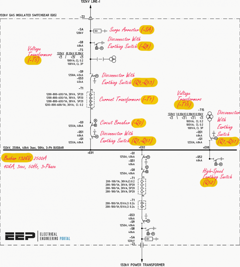
- Comprehending the Elements of a Substation Single Line Diagram:
- Exploring the Interlocking Scheme in a 132 kV Gas-Insulated Substation:
- Utilizing an Interlock Table in Gas Insulated Switchgear (GIS) Design:
- Three States of Equipment in Interlocking Table (Open and Close Status, Not in Intermediate Position)
- 132kV Line Bay Interlocks:
- 132kV Transformer Bay Interlocks
- Potential Transformer Bay Operation (E00)
- BONUS: Download 132/11.5 kV GIS Interlocking Diagram & Table (PDF)
1. Gaining Familiarity with Essential Electrical Terminology
To gain a comprehensive understanding of interlocking mechanisms within a Gas Insulated Substation, it is prudent to commence with a solid grasp of the core terminology that forms the foundation of this topic.
This initial step will provide you with the necessary knowledge to navigate the intricate details of interlocking systems within the context of a Gas Insulated Substation.
1.1 Exploring Gas-Insulated Switchgear (GIS)
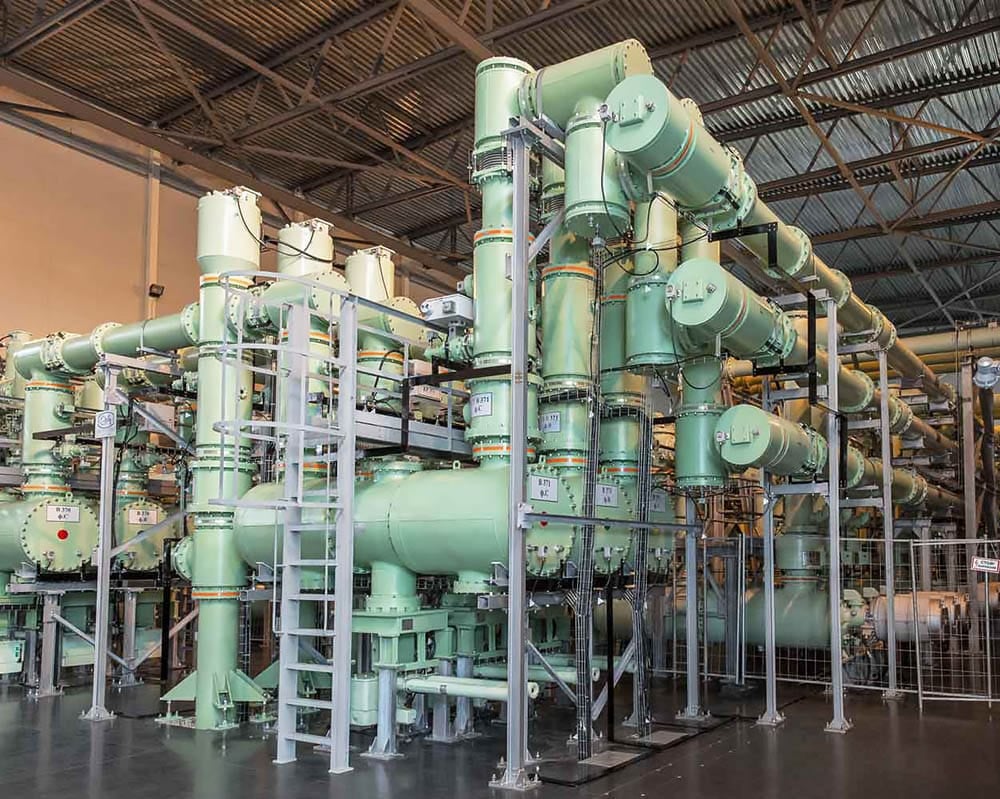
In the realm of electrical engineering, a Gas-Insulated Switchgear (GIS) represents a highly sophisticated composite system. It is ensconced within a robust metal frame, which acts as a protective housing for a multitude of essential electrical components. These components include circuit breakers, bus bars, transformers, earth switches, surge arrestors, and more.
What sets GIS apart is the fact that all these intricate devices reside within sealed compartments, immersed in sulfur hexafluoride gas (SF6). These compartments are effectively shielded, creating a secure environment for electrical operations.
Figure 1 – Gas-Insulated Substation (GIS)
1.2 Grasping the Role of a Switch
A switch, within the context of electrical circuits, is a device designed to establish and disrupt the flow of electricity. You can visualize a simple example of this in your everyday life – a room’s light switch. This familiar household switch controls whether the room’s lights are turned on or off.
In a more complex setting like a substation, switches take on more specialized forms. Disconnectors, Earthing Switches, and Circuit Breakers serve as prime examples, responsible for managing the flow of electricity within the substation’s intricate network.
1.3 Defining Load in Electrical Terms
Within the electrical domain, the term “load” refers to any equipment or group of equipment that draws a measurable current from the electrical system. This current, termed “load current“, signifies the electrical demand placed upon the system.
Typical examples of loads encompass transformers and GIS substations that receive electrical current from a line feeder, playing a pivotal role in the broader network’s functionality.
Good Reading – Parameters of generators, transformers, lines and cables for vars, voltage and loads control
Parameters of generators, transformers, lines and cables for vars, voltage and loads control
1.4 Distinguishing On Load Switching
On-load switching describes the condition where turning on a switch allows the flow of current through it. An imperative characteristic of on-load switching is its need for rapid execution to mitigate the formation of electrical arcs.
Circuit breakers are an exemplar of devices equipped for on-load switching, and their swift response times are pivotal in preserving system integrity.
1.5 Exploring Off-Load Switching
Conversely, off-load switching represents the scenario in which activating a switch does not permit the passage of current through it. When an off-road switch is engaged, the voltage present will continue to the next point in the circuit after the switch. Unlike on-load switching, off-load switching doesn’t necessitate swift actions; typical opening and closing times for off-load switches occur over seconds.
Disconnectors and earthing switches are representative of devices designed for off-load switching, playing a vital role in safeguarding the system during maintenance or isolation procedures.
Suggested Guide – The essentials of power systems analysis for electrical engineers, students and researchers
The essentials of power systems analysis for electrical engineers, students and researchers
1.6 Understanding Arcing and Its Implications
Arcing involves the creation of a powerful, intensely luminous current discharge. This phenomenon transpires when a substantial electrical current jumps across a gap between two electrodes. In certain industrial applications, arcing serves a purpose, such as in illumination or welding processes where the brilliance of the arc is essential. However, in the context of substations and power systems, undesired arcing can lead to detrimental consequences.
Unwanted arcing jeopardizes the structural integrity of both moving and stationary components within the system and must be rigorously prevented to ensure safe and reliable operation.
Related electrical guides & articles


Muhammad Kashif
Muhammad Kashif Shamshad is an Electrical Engineer and has more than 17 years of experience in operation & maintenance, erection, testing project management, consultancy, supervision, and commissioning of Power Plant, GIS, and AIS high voltage substations ranging up to 500 kV HVAC & ±660kV HVDC more than ten years experience is with Siemens Saudi Arabia.Profile: Muhammad Kashif
