Testing Metal-Clad Switchgear
This article aims to provide a comprehensive analysis of the essential inspection and testing processes, emphasizing their importance in the effective functioning of medium-voltage switchgear. The inspection and testing standards included in this resource prioritize safety, functionality, and efficiency, making them an invaluable tool for upholding the integrity of medium-voltage switchgear within power distribution networks.
 Prepare yourself for successful inspection and testing of MV metal-clad switchgear (photo credit: Enersol Engineering)
Medium-voltage switchgear plays a pivotal role in the reliable distribution of electricity, safeguarding electrical systems, and ensuring the safety of people and equipment. As these switchgear units are essential components of power distribution systems, their integrity and performance are of utmost importance.
To guarantee the uninterrupted flow of electricity and avert potential hazards, it is crucial to inspect, maintain, and test medium-voltage switchgear regularly.
The key inspection and testing procedures can be divided into several categories:
Physical Inspection – This category encompasses assessing the overall physical condition of the switchgear, inspecting enclosures, covers, panels, and bus systems, and checking for any visible defects or damage.
Alignment and Foundation – Proper alignment, foundation fixing, and grounding are critical for ensuring the switchgear’s stability and safety. These aspects are covered in the inspection.
Mechanical Checks – Various mechanical components such as racking mechanisms, circuit breakers, and switches are evaluated for smooth operation, proper alignment, and interlock functionality.
Electrical Testing – This includes insulation resistance tests, functional tests of controls and interlocks, continuity and phasing tests, and resistance tests.
Specific Breaker Checks – Procedures specific to the type of circuit breaker in use, such as air magnetic breakers, minimum oil breakers, or SF6 breakers, are detailed, covering gas pressure, arc chutes, and oil quality, among others.
In this article, we will explore each of these procedures in detail, highlighting the significance of their implementation and their role in ensuring the reliable performance of medium-voltage switchgear.
With an emphasis on safety, functionality, and efficiency, these inspection and testing guidelines are a valuable resource for maintaining the integrity of medium-voltage switchgear in power distribution systems.
- Ensuring Reliability and Safety: In-Depth Mechanical Checks and Visual Inspections
- Visual Inspect for physical damage or defects
- Check nameplate information for correctness
- Verifying the Proper Alignment of Circuit Breaker Primary and Secondary Contacts
- Check the Operation of All Mechanical Interlocks
- Key Locks Testing
- Mechanical Interlocks Between Switching Devices and Earthing Switch
- Testing Withdrawable Voltage Transformer Sets
- Verifying the Tightness of Bolted Connections in Medium Voltage (MV) Switchgear using the Torque Wrench Method
- Verifying the Correct Phasing of Main and Riser Buses
- Inspecting Mechanical Flags and Status Indicators for Circuit Breakers, Springs, Isolators, Earth Switches, etc., Through Operational Testing
- Electrical Check List and Testing of Medium Voltage (MV) Switchgear
- Insulation Resistance Testing of All Circuits in MV Panel
- Checking AC/DC Miniature Circuit Breakers (MCBs) in the Panel for Correct Ratings, Grading, and Conducting Trip Tests by Current Injection
- Main Circuit Resistance Test for MV Switchgear
- Performing Electrical Tests on Equipment in Medium Voltage (MV) Switchgear
- Elaboration on Medium Voltage (MV) Circuit Breaker Tests
- Current Transformer Test
- Voltage Transformer Test
- Disconnect and Grounding Switch Tests
- BONUS! Industrial Power Systems Handbook (PDF)
1. Ensuring Reliability and Safety
In-Depth Mechanical Checks and Visual Inspections for Medium Voltage Metal Clad Switchgear
In the realm of medium voltage switchgear, mechanical checks and visual inspections play a pivotal role in ensuring the reliability, safety, and longevity of the equipment. This section of the comprehensive guide focuses on the meticulous scrutiny and assessments related to the mechanical components of medium voltage switchgear.
The mechanical checklist is in accordance with the standard IEC 62271-100 and outlines a systematic approach to mechanical checks and visual inspections for metal-clad switchgear.
This also involves adherence to specific criteria and procedures designed to safeguard the reliability and safety of the equipment.
1.1 Visual Inspect for physical damage or defects
A visual inspection is the initial step in assessing the condition of metal-clad switchgear. It involves a comprehensive examination of the exterior of the equipment. During this phase, the following aspects are scrutinized.
Ensure that all enclosures, panels, and doors are in the correct position and properly aligned. Examine for any signs of misalignment, warping, or damage that may affect the enclosure’s ability to provide protection against environmental factors or provide a barrier to prevent accidental contact with live parts.
Look for signs of chipping, flaking, or peeling paint, which can indicate underlying corrosion or exposure to harsh environmental conditions.
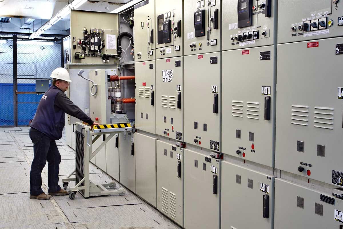
Figure 1 – Medium voltage metal-clad switchgear
1.2 Check Nameplate Information for Correctness
Within the inspection process, it is imperative to thoroughly examine the nameplates affixed to each piece of equipment and cross-reference them with the officially approved detailed design documentation. These nameplates contain vital information about various components, including relays, auxiliary relays, current transformers, voltage transformers, and bus bars.
It is essential to verify that the information on these nameplates, such as ratings, manufacturer details, and origin, precisely matches the specifications outlined in the approved design.
This stringent approach ensures that the switchgear adheres to the specified standards and design parameters, upholding the integrity and safety of the electrical system.
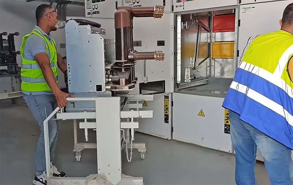
Figure 2 – Racking out MV circuit breaker using dedicated trolley
1.3 Verifying the Proper Alignment of Circuit Breaker Primary and Secondary Contacts
Ensuring the correct alignment of the primary and secondary contacts within a circuit breaker is a pivotal element of inspecting metal-clad switchgear. This alignment is of utmost importance as it directly impacts the electrical connections and overall functionality of the circuit breaker.
Let us elaborate on the significance and process of checking for the proper alignment of the circuit breaker’s primary and secondary contacts:
Significance – The primary contact within a circuit breaker are responsible for establishing and interrupting electrical circuits, whereas secondary contacts are used to indicate status if circuit breaker.
Proper alignment of these contacts is crucial for several reasons: