
Estimated Study Time: 28 minutes
Electrical Schematics, Symbols & Isolation
This technical article aims to delve into various aspects of electrical schematics, symbol representation, and isolation methodologies, shedding light on fundamental concepts and practical applications within the field. From the intricacies of electrical connection and circuit topology to the symbolism and functionality of shielded cables, this article navigates through essential topics essential for engineers, technicians, and enthusiasts alike.
 Mastering Electrical Schematics: From Circuit Topology to Switching Classifications
We explore the significance of electrical contact, the nuances of signal routing, and the classifications of digital switching within schematics.
Additionally, we delve into the world of isolators, understanding their role as off-load devices and the factors influencing their selection in power systems.
Central to our discussion are the concepts of Single Point Indication (SPI) and Double Point Indication (DPI), pivotal in monitoring switch positions within substations and industrial settings. With a historical perspective and practical insights into their applications, we uncover the importance of these indication statuses in ensuring safety and efficiency in electrical systems.
- Electrical Connection/Wiring:
- Electrical Contact:
- Contact Free Crossing of Wires:
- Understanding Shielded Cables: Symbolism and Applications in Electrical Diagrams:
- Types of Electrical Isolators
- Key Characteristics and Functions:
- Classification Based on Power System Location
- Factors to Consider When Choosing Isolators
- Classification of the Digital switching in the Schematics:
- Single-Point and Double-Point Indication Status:
- BONUS (PDF) 🔗 Download Practical Guide to Relay Protection For True Power System Engineers
1. Electrical Connection/Wiring
The wire symbol is typically represented by a straight line connecting two or more components or nodes within the circuit. It may appear as a simple line segment or a series of interconnected lines, depending on the complexity of the circuit and the number of connections involved.
In schematic diagrams, wires are drawn without regard to their physical layout, allowing for a clear and concise representation of the circuit topology.
Figure 1 – The line symbol serves the purpose of linking various devices within the schematic diagram

1.1 Electrical Connectivity
The primary function of the wire symbol is to illustrate electrical connectivity between components or nodes in the circuit. Each wire represents a conductive path through which electric current can flow, enabling the transfer of energy and signals between interconnected elements.
1.2 Circuit Topology
By tracing the paths of wires in a schematic diagram, engineers and technicians can discern the circuit’s topology and understand how components are interconnected. This aids in analysing circuit behaviour, identifying potential issues, and designing modifications or improvements.
1.3 Signal Routing
Wires in schematic diagrams also serve as conduits for routing signals between different sections of the circuit. By following the paths of wires, designers can determine how signals propagate through the circuit and ensure proper signal integrity and functionality.
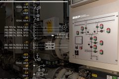
Figure 2 – 132 kV line isolator operation schematic
1.4 Visual Clarity
The wire symbol contributes to the clarity and readability of schematic diagrams by providing a clear representation of electrical connections without cluttering the diagram with unnecessary detail. Its simplicity allows engineers to focus on the overall circuit design and functionality.
1.5 Example and Application
Consider a simple circuit consisting of a battery, a resistor, and an LED connected in series. The wire symbol would be used to illustrate the connections between these components, depicting the flow of current from the battery through the resistor, then through the LED, and back to the battery.
By following the paths of wires in the schematic diagram, one can visualize how the components are electrically connected and understand the circuit’s operation.
Figure 3 – The battery, resistor, and LEDs are interconnected in the schematic diagram using wires
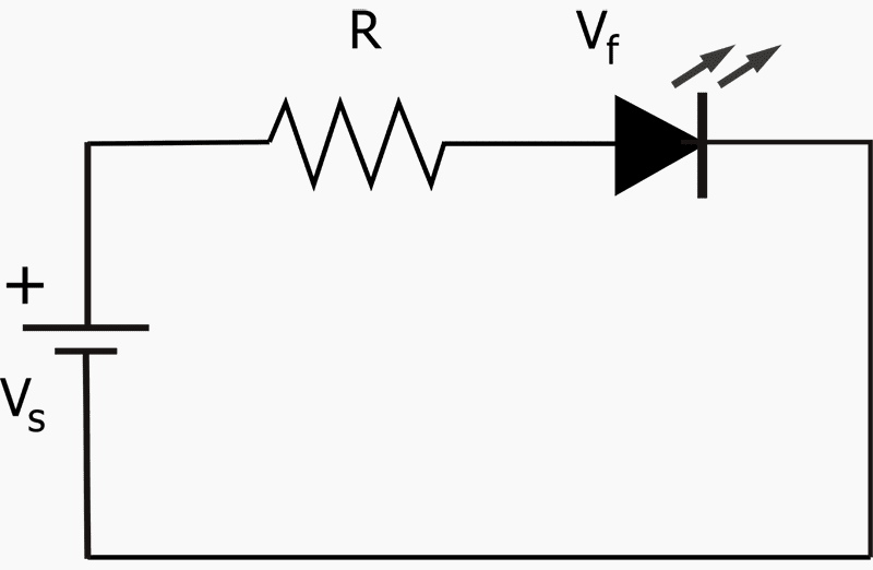
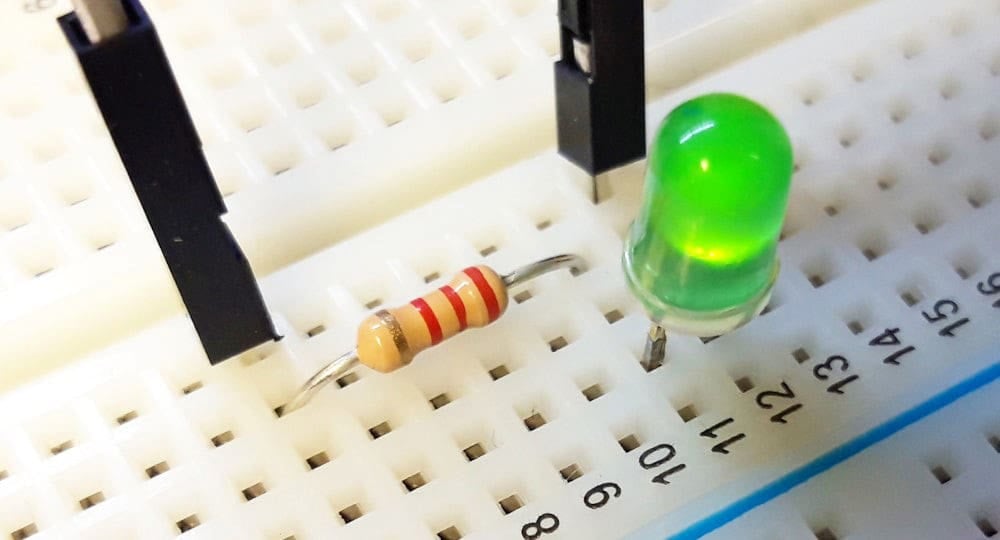
Figure 4 – The battery, resistor, and LED are physically connected on the breadboard using wires
2. Electrical Contact
The electrical connection symbol in electrical diagrams is a representation used to indicate how electrical components or elements are interconnected within a circuit. It signifies points of electrical continuity or junctions where wires or conductors meet. Here’s a detailed explanation:
2.1 Symbol Appearance
The electrical connection symbol typically consists of a dot or a small circle placed at the intersection point of two or more lines representing wires or conductors in the circuit diagram. It’s important to note that this symbol does not denote a physical component but rather a point where electrical continuity is established.
2.2 Meaning and Functionality
The presence of the electrical connection symbol indicates that the wires or conductors connected at that point are electrically continuous. In other words, it signifies that current can flow freely between those wires without interruption.
Node Connections: In complex circuits, nodes represent points where multiple wires or conductors intersect. The electrical connection symbol is used at these nodes to clarify that all intersecting wires are electrically connected.
Component Connections: The electrical connection symbol also denotes how wires are connected to various components in the circuit. For example, it may indicate where a wire connects to the terminals of a resistor, capacitor, transistor, or any other electronic component.
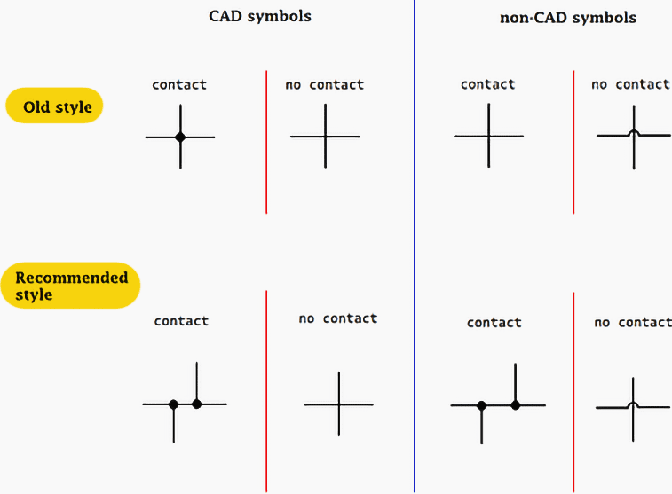
Figure 5 – Wire connection methodology used in CAD and non-CAD symbols
3. Contact-Free Crossing of Wires
In schematics, a contact-free crossing of wires, also known as a “jump” or “flyover”, occurs when two wires cross each other without actually connecting electrically. This is often necessary to improve the readability of the diagram or to avoid cluttering when drawing complex circuits.
There are several ways to represent a contact-free crossing of wires in schematics:
Related electrical guides & articles


Muhammad Kashif
Muhammad Kashif Shamshad is an Electrical Engineer and has more than 17 years of experience in operation & maintenance, erection, testing project management, consultancy, supervision, and commissioning of Power Plant, GIS, and AIS high voltage substations ranging up to 500 kV HVAC & ±660kV HVDC more than ten years experience is with Siemens Saudi Arabia.Profile: Muhammad Kashif
