
Estimated Study Time: 28 minutes
The Accuracy of Fault Detection
The first part of this article series delved into the fundamentals of overcurrent protection, exploring the intricacies of relay coordination, the impact of source impedance, and the application of distance protection. These foundational concepts laid the groundwork for understanding how protective devices function within an electrical network, particularly in relation to overcurrent and distance protection schemes.
 Mastering Distance Protection and Calculations Part 2: Arc Resistance, Impedances and CTs/VTs
As we advance into the second part of this series, we shift our focus towards more specialized topics that further refine our understanding of protection systems. This part will explore the complexities introduced by factors such as arc resistance, reflected impedances, and the critical role of current and voltage transformers in distance protection.
These elements are crucial in determining the accuracy of fault detection and the overall performance of protection systems.
One of the key challenges in distance protection is the correct setting and calibration of relays to account for real-world variables. These include the transformation of impedance through current and voltage transformers, which directly influences the relay’s ability to detect and isolate faults effectively. Misjudgments in these settings can lead to either underreaching or overreaching of the protection zones, potentially compromising the stability of the power system.
Additionally, we will examine the evolution of relay settings and how modern protection schemes have adapted to address emerging challenges. A particular focus will be on the Switch-On-to-Fault (SOTF) feature, a critical function designed to prevent severe network disturbances during specific fault conditions.
Understanding the operation and importance of the SOTF feature is essential for engineers tasked with maintaining the integrity of the power grid.
Finally, the phenomenon of load encroachment in long transmission lines will be explored, with particular attention to its impact on distance protection, specifically Zone 3. The potential for maloperation in this zone can lead to cascading failures, underscoring the need for meticulous relay setting calculations and advanced protection strategies.
By building on the foundational knowledge established in the first part, this article aims to equip engineers with a deeper understanding of the nuanced factors that influence protection accuracy, ultimately contributing to more robust and reliable power system operations.
- Impact of Arc Resistance on Line Impedance and Protection Accuracy
- Reflected Impedances in Distance Protection
- Switch-On-to-Fault (SOTF) Feature in Protection Systems
- Understanding Residual and Zero-Sequence Compensation Factors in Ground Distance Relays
- Load Encroachment in Long Transmission Lines
- BONUS (PDF) 🔗 Download Protective Relaying Handbook – Concepts and Implementations
1. Impact of Arc Resistance on Line Impedance and Protection Accuracy
When a fault occurs on a transmission line, an electrical arc is often produced at the fault location. This arc not only conducts electricity but also introduces a certain amount of resistance, known as arc resistance. The presence of arc resistance affects the overall impedance of the line, as it adds to the existing line impedance.
In a fault-free scenario, the line impedance is primarily determined by the physical properties of the line, including its resistance and reactance. These parameters define the line angle, which is the phase angle of the impedance and typically remains constant under normal conditions. However, when a fault occurs and an arc is formed, the additional resistance from the arc alters the total impedance seen by protective relays.
As a result, the line angle, which is the ratio of the reactance to the total resistance (including arc resistance), is also modified.
This modification of the line angle is important in the context of protection schemes, particularly distance protection, which relies on accurate impedance measurements to determine the fault location. If the line angle is significantly altered by arc resistance, it can lead to inaccuracies in fault detection and potentially compromise the effectiveness of the protective relay.
When a fault occurs on a transmission line, the resulting arc introduces resistance that modifies the line impedance and, consequently, the line angle. This change in line angle is more significant in shorter lines, where the arc resistance forms a larger proportion of the total impedance, potentially impacting the performance of protective relays and the accuracy of fault detection.
Lesson – Arc resistance and its effect on relay performance
Lesson – Line angle
2. Reflected Impedances in Distance Protection
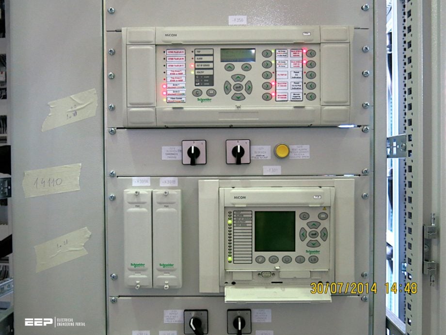
In the context of distance protection, understanding the concept of reflected impedance is crucial for accurate fault detection and relay operation. Reflected impedance refers to the impedance as seen by the protective relay after accounting for the transformation ratios of the current transformers (CTs) and voltage transformers (VTs) used in the protection scheme.
2.1 Current and Voltage Transformers
Current transformers (CTs) and voltage transformers (VTs) are used to step down high system voltages and currents to lower, more manageable levels that can be safely measured by protective relays. The CT reduces the primary current flowing through the transmission line by a specified ratio, while the VT does the same for the voltage.
For example, consider a CT with a ratio of 800:1. If 400 amps are flowing through the primary side of the CT, the current seen by the relay on the secondary side would be 0.5 amps. Here, 400 amps is the primary current, and 0.5 amps is the secondary current.
Similarly, if a VT steps down a high voltage using its ratio, the relay measures a proportionally lower secondary voltage.
Worth Reading – The most frequent errors in specifying current transformers
The most frequent errors in specifying current transformers (CTs)
2.2 Correct Setting and Calibration
When setting up distance protection, the CT and VT ratios must be correctly configured in the relay settings. This ensures that the impedance calculated by the relay reflects the true impedance of the line as seen from the relay’s perspective.
If the transformation ratios are not accurately set, the relay may misinterpret the fault distance, either underreaching or overreaching, potentially leading to incorrect tripping or failure to trip when necessary.
Related electrical guides & articles


Muhammad Kashif
Muhammad Kashif Shamshad is an Electrical Engineer and has more than 17 years of experience in operation & maintenance, erection, testing project management, consultancy, supervision, and commissioning of Power Plant, GIS, and AIS high voltage substations ranging up to 500 kV HVAC & ±660kV HVDC more than ten years experience is with Siemens Saudi Arabia.Profile: Muhammad Kashif
