
Commissioning Challenges
Commissioning of a power plant or an industrial plant is not that simple, on contrary, it’s full of hidden traps and logical challenges. In power plants, the generating units are substantial operational blocks, tested individually alongside the water or fuel pathways (input) and the electrical route from low-voltage switchgear to the high-voltage switchyard (output), in conjunction with the unit services and operational controls simultaneously. Station services are usually commissioned independently.
 Solving Problems in Commissioning of Industrial and Power Plants
On the other hand, the facility operating system can be divided into smaller subsystems, such as crushing and milling, which can be precommissioned and commissioned independently.
Extreme caution is required at all times by anyone operating the equipment during testing and commissioning to prevent the accidental activation of circuit-breakers, disconnectors, motors, etc. Serious harm can be inflicted by released tensioned springs, rotating shafts, levers, and similar devices.
Consideration of the possibility of shocks and injuries caused by falling from ladders, etc., is also necessary.
Disconnecting electrically operated equipment’s control circuits and, if feasible, mechanically securing it helps prevent accidents like these.
- Precommissioning Activities:
- Wet and Dry Commissioning:
- Checking the Reliability of Power Plant Systems (CR)
- Power Plant Grid Tests
- Commissioning Reports
- Attachment (PDF) 🔗 Download ‘Power Plant Commissioning Guide’
1. Precommissioning Activities
The precommissioning and commissioning of an industrial or power plant are distinct tasks. They must be treated differently, especially if the facility systems are totally automated.
1.1 Secondary Injection to CTs & PTs Circuits
Meggering and high-pot testing of the switchgear are the initial steps. Next, in accordance with the protective relay setting sheets for every circuit breaker, the protective relays are tested by secondary injection (simulation) to trip the breakers caused by overloads or undervoltages.
The circuits of protective current transformers (CTs) and potential transformers (PTs) are supplied to the tester to simulate the operational condition.
A three-phase tester, depicted in Figure 1, conducts the secondary injection.
Figure 1 – Secondary injection test kit

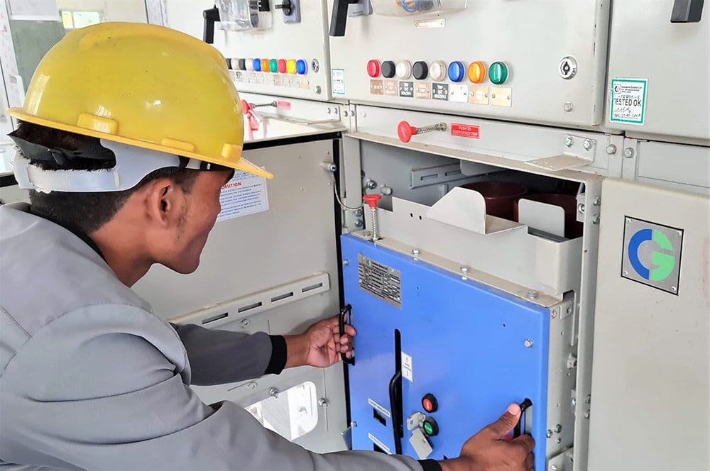
1.2 Circuit Breakers (Drawn-in, Test and Drawn-out Conditions)
Each circuit breaker in the switchgear can be tested for operation in its drawn-in (actually connected), test, and withdrawn (disengaged) positions. The switchgear is de-energized; however, the circuit breakers remain operable due to the electrically powered 125 V DC control circuits, enabling their functionality.
Additionally, an additional control circuit operating at 24 V AC or DC may be utilized for remote operation and communication with the plant control system. In each of the three positions, the switchgear and circuit breaker make their presence known and marked.
The test position is extremely helpful during the commissioning (energized) phase of plant testing that occurs prior to precommissioning.
Comparable precommissioning actions are conducted on MCCs for each motor or feeder circuit to facilitate the energization of the assembly and to supply power to motors and feeders for further testing. Each motor is being adjusted to synchronize its rotation with that of the pumps or conveyor movements, etc. The motors are decoupled from the pumps for this task.
Additionally, the motor branch circuit breakers undergo pretesting to determine their minimum instantaneous protection settings appropriate for the motor inrush currents.
Figure 2 – Technician drawing out the VCB trolley for testing
1.3 Testing Cable Wiring
Extensive simulations will be necessary during precommissioning to evaluate the equipment and cable wiring. This requires bridging the connections and applying voltage or current from other sources to control the operation of the switchgear breakers or motor control center starters. All wiring and schematics of field devices and hardwired safety interlocks must be verified.
Wiring diagrams were previously verified during the precommissioning phase; however, they are now increasingly uncommon as they become outdated.
Wiring diagrams have been significantly simplified through the utilization of communication channels, including Ethernet, DeviceNet, Modbus, and others. The newest schematics have all the terminals labeled identically to the previously used wiring diagrams.
It appears to be a prevailing trend currently. While not yet evident in all industrial projects, it is undeniably a trend in large power plants.
Related electrical guides & articles


Edvard Csanyi
Hi, I'm an electrical engineer, programmer and founder of EEP - Electrical Engineering Portal. I worked twelve years at Schneider Electric in the position of technical support for low- and medium-voltage projects and the design of busbar trunking systems.I'm highly specialized in the design of LV/MV switchgear and low-voltage, high-power busbar trunking (<6300A) in substations, commercial buildings and industry facilities. I'm also a professional in AutoCAD programming.
Profile: Edvard Csanyi
