To Protect the Transmission Line Under Fault
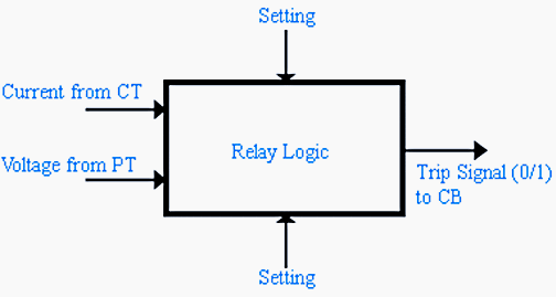
Formally, a relay is a logical element which processes the inputs (mostly voltages and currents) from the system/apparatus and issues a trip decision if a fault within the protection relay‘s jurisdiction is detected.
A conceptual diagram of relay is shown in Figure 1 below.
Let’s see an example
In Figure 2 below, a relay R1 is used to protect the transmission line under fault F1. An identical system is connected at the other end of the transmission line relay R3 to open circuit from the other ends as well.
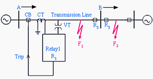
To monitor the health of the apparatus, relay senses current through a current transformer (CT), voltage through a voltage transformer (VT). VT is also known as Potential Transformer (PT).
The relay element analyses these inputs and decides whether:
- There is a abnormality or a fault and
- If yes, whether it is within jurisdiction of the relay.
The jurisdiction of relay R1 is restricted to bus B where the transmission line terminates. If the fault is in it’s jurisdiction, relay sends a tripping signal to circuit breaker CB which opens the circuit.
If there is an obstruction to the regular flow due to fault F1 or F2, the traffic police (relay R1) can sense both F1 and F2 obstructions because of resulting abnormality in traffic (power flow). If the obstruction is on road AB, it is in the jurisdiction of traffic police at R1; else if it is at F2, it is in the jurisdiction of R2. R1 should act for fault F2, if and only if, R2 fails to act.
We say that relay R, backs up relay R2. Standard way to obtain backup action is to use time discrimination i.e., delay operation of relay R, in case of doubt to provide R2 first chance to clear the fault.
Reference: Fundamentals of power system protection – Paper





useful articles indeed
I really like your analogy and very useful information’s
Thank you