
Estimated Study Time: 22 minutes
Typical Loads Supplied
Substation AC auxiliary systems are typically used to supply loads such as transformer cooling, oil pumps, and load tap changers, circuit breaker air compressors and charging motors, outdoor device heaters, outdoor lighting and receptacles, motor-operated disconnecting switches and control house.
 AC Auxiliary Systems In Power Substations (Design Requirements and Equipment)
Control house usually includes lighting and receptacles, heating, ventilating and air conditioning, battery charger input and water well pump.
Now, let’s discuss the following topics about main design requirements for typical AC auxiliary system in a power substation and electrical equipment used for implementing:
- Design Requirements:
- Equipment For AC Auxiliary Systems:
- Summary
Design Requirements
1. Demand Load
Tabulate the connected kVA of all substation AC loads and apply a demand factor to each. Demand kVA is used to size the auxiliary transformer(s). Load diversity and load factor need not be considered in this case.
In auxiliary transformer sizing, examine the substation growth rate.
2. Number of Primary Feeds
In small distribution substations one auxiliary transformer is usually sufficient. As substation size increases, customer load criticality increases. A decision has to be made as to redundancy of substation auxiliary services in light of economics and customer requirements.
When dual feeds are selected, locate two separate, independent sources so the loss of one will not affect service of the other. Designate the least reliable as the alternative supply. A popular option to consider in this case is the use of a tertiary winding of the power transformer as a normal source.
An alternative source could be a distribution feeder at a customer service level, 480 or 240 volts, single or three phase. Depending on auxiliary secondary voltage level selected, this could eliminate one transformer.
3. Overhead or Underground Entry
The auxiliary source(s) could be either overhead or underground distribution lines. When undergrounding within the substation property, even from an overhead source, direct-buried conduit is recommended. A spare, capped, conduit should be installed to minimize down time if a cable failure occurs.
The faulted cable can always be removed after service restoration.
4. Critical Loads
Some low-voltage loads have to be maintained at all times:
- Battery chargers which, through the batteries, supply breaker trip and close circuits as well as communication circuits
- Transformer cooling
- Power circuit breaker compressors and motors
- Trouble light receptacles in the station yard
- Security lighting
- Breaker control circuits
- Fire alarm circuit(s)
- Electric heating
- Substation automation circuitry
Critical loads for each station should be determined. These loads should be served from a panel(s) fed from the normal source and representing the minimum load for transfer to alternative supply.
5. Secondary Voltage Level
Several secondary voltage or utilization levels are available for AC auxiliaries. For the purposes of standardization, on a given power system it is best that only one level be selected. This is not a limiting rule, however. An exception could be justified.
Possible secondary voltage levels are as follows:
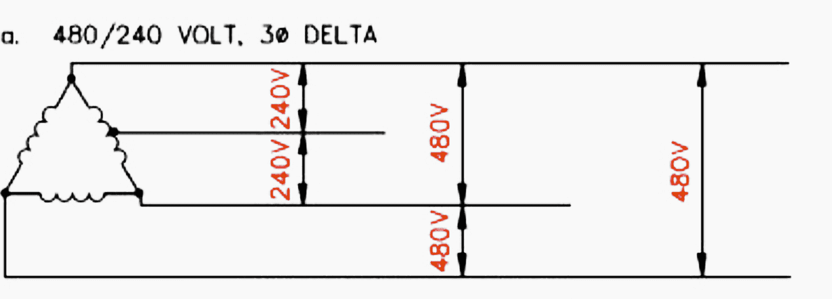
1. 480/240 Volts, Three-Phase Delta
Three-phase transformer fans and oil pumps need to be specified at 480 volts. In practice, the units are rated at 460/230 volts, but this is inside the NEMA plus 10 percent voltage requirement. Other loads may be specified at either 480 or 240 volts, single phase.
This system is ungrounded and should be used with a ground detection system so that a “fault” or one leg of the system will cause an alarm. The system should trip when a second leg on the system is grounded.
2. 480/277 Volts, Wye Connected, Three-Phase, Four-Wire
Three-phase transformer fans and oil pumps need to be specified at 480 volts. In practice, motors are rated 460/230 volts, but this is within the NEMA plus 10 percent voltage requirement.
Convenience receptacles are fed through small dry-type 480-120 volt transformers.
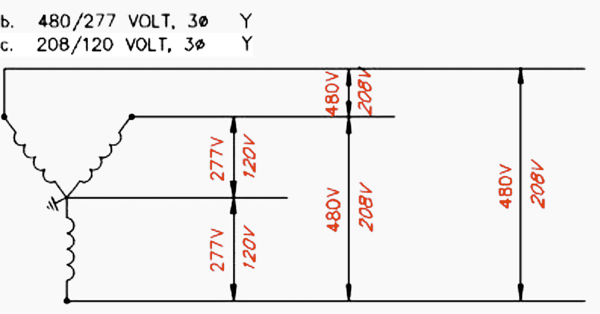
3. 208/120 Volts, Wye-Connected, Three-Phase, Four-Wire
Three-phase 208 volts or single-phase 120 volts or a combination of the two can be used for transformer cooling (Figure 3). Combination power and lighting panels can be used, resulting in reduced labor and material costs. This saving could be offset by higher conductor costs as compared to the 480-volt system.
Receptacles can be served with 120 volts directly.
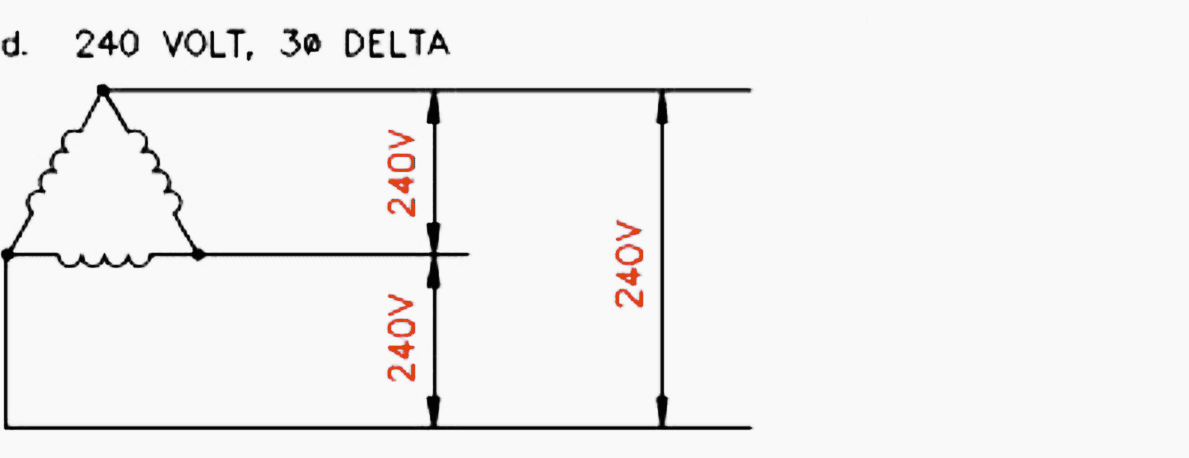
4. 240 Volts, Three-Phase Delta
Three-phase transformer fans and oil pumps need to be specified at 240 volts. In practice, the motors are rated at 230 volts, but this is inside the NEMA plus 10 percent voltage requirements.
This system is ungrounded and should be used with a ground detection system so that a “fault” on one leg of the system will cause an alarm. The system should trip when a second leg on the system is grounded.
5. 240/120 Volts, Delta-Connected, Three-Phase, Four-Wire
This is the most common level in use in moderate-size substations. One phase of the auxiliary transformer is center tapped to obtain 120 volts.
Combination panels can be used, and 240-volt single-phase loads can be served.
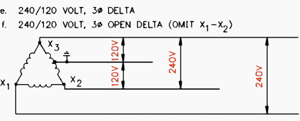
6. 240/120 Volts, Open Delta-Connected, Three-Phase, Four-Wire
This is essentially the same as the closed delta connection except only 58 percent of the kVA capacity of the three transformers can be used. This configuration (Figure 5) will provide construction economy for a medium-size installation or for temporary use.
With single-phase units, the third transformer can be added in the future for increased kVA capacity.
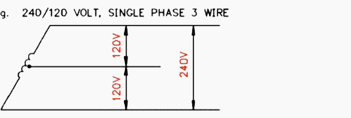
7. 240/120 Volts, Single-Phase, Three-Wire
This is “residential” service but applicable to small substations. Common panels can be used, with two available voltages.
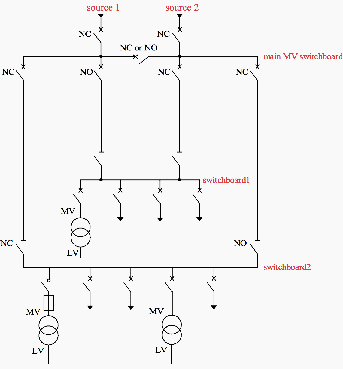
6. Transfer Scheme
Where two sources, normal and alternative, are feeding substation auxiliaries, a means to transfer from one to the other has to be established. At an attended station this can be a manual transfer arrangement. Automatic transfer has to be provided at an unattended station.
Transfer is done on the secondary side for equipment economy.
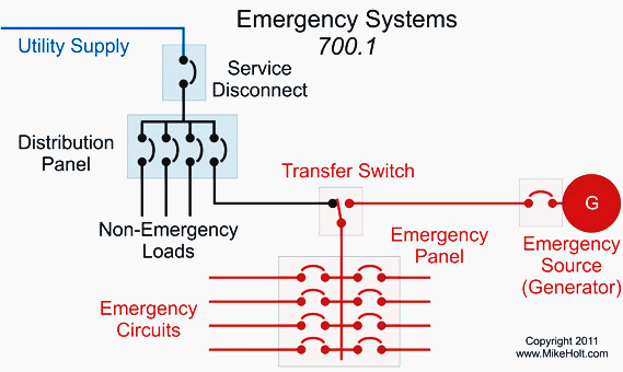
Article 700 of the National Electrical Code (NEC) as shown in figure 7 – outlines general requirements for this type of scheme. A typical configuration is shown in Figure 8.
The switch should have an ampere withstand capability for faults at points A, B, and C of Figure 8. The fault at C will be highest, the feeder impedance to B and A limiting the fault current to an amount below that at C.
The auxiliary system in Figure 7 assumes transfer of all loads. The full load current of the 150 kVA transformer is 360 amperes, so a 400-ampere switch would be selected.
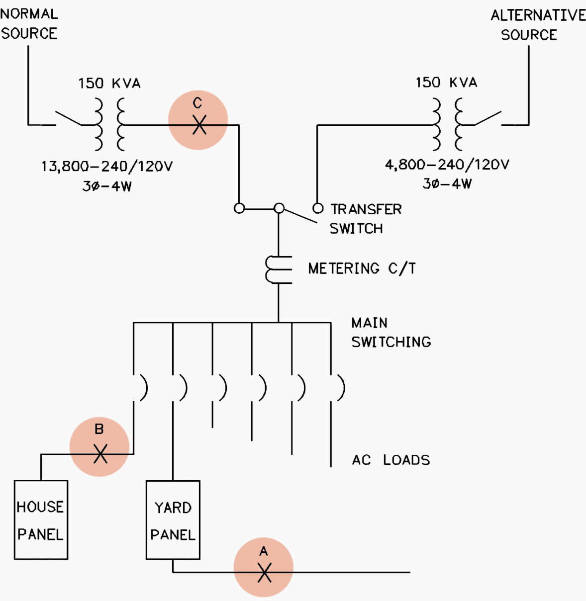
Assuming a 250,000 kVA source, two 500 kcmil, 3.05-meter (10-foot) feeders per phase to the switch, and 4 percent transformer reactance, the fault current is approximately 10,000 amperes. This value is well within manufacturers’ standard ratings for 400-ampere full load transfer switches.
Manufacturers’ data is readily available, and the engineer should consult such data when specifying a transfer switch. Provide means to alarm for loss of voltage from either source.
7. Auxiliary System Fault Currents
The determination of fault currents in three-phase ac auxiliary systems is just as basic as the determination of load currents in sizing circuit breakers or fuses. The protective device has to operate or open during faults as well as carry load current during normal conditions or equipment damage could result.
The symmetrical short circuit (fault) current is computed using Equation 1:
IF = Line-to-Line kV / (√3 × Ohms Resistance)
Ohms reactance is the total reactance of all current-carrying parts from the source to the fault.
The asymmetrical fault current is a function of the fault circuit X/R ratio. A multiplying factor (1.7) for the asymmetrical current is satisfactory for auxiliary power system calculations.
Fuse and circuit breaker manufacturers have handbooks with X, R, and Z values for transformers, current transformers, cables, etc., together with methods for determining protective device ratings based on estimated fault currents.
Equipment For AC Auxiliary Systems
1. Transformers
ANSI Std. C57.12.25 and ANSI Std. C57.12.26 are applicable for selection of AC auxiliary system pad-mounted transformers. This type of transformer is good for large substation auxiliary service use
The secondary voltage levels listed in above Section ‘Secondary voltage level’ are manufacturers’ standards. Consider the feasibility of establishing substation auxiliary system voltage at the same level as that for serving underground customers. With this standardization, spare transformers can be stocked and both customer and substation service maintained at minimum cost.
If the normal and alternative sources are overhead, pole-mounted, and hook stick operated, fused switches are a possible solution to transformer primary protection. Underground cable is used for the connection from the switches to the transformer pad.
ANSI Std. C57.12
ANSI Std. C57.12.25 – Pad-Mounted Compartmental-Type, Self-Cooled, Single-Phase Distribution Transformers with Separable Insulated High-Voltage Connectors; High Voltage, 34500 GRD Y/19920 Volts and Below; Low Voltage, 240/120 Volts; 167 kVA and Smaller.
ANSI Std. C57.12.26 – Pad-Mounted Compartmental-Type Self-Cooled, Three- Phase Distribution Transformers for Use with Separable Insulated High-Voltage Connectors, High Voltage, 34500 GRD Y/19920 Volts and Below; 2500 kVA and Smaller.
Pad-mounted transformers and the kVA ratings previously mentioned apply to a fairly large substation. For smaller installations, structure-mounted distribution transformers, properly applied, can be used.
2. Electrical Panelboards
The definition of a branch circuit panelboard in the NEC (Article 384) is one having more than 10 percent of its overcurrent devices rated 30 amperes or less for which neutral connections are provided. Additionally, the number of branch circuit devices in one enclosure is limited to 42 poles.
Switchboards differ from panelboards in that switchboards are free standing. Front or rear access to line and load terminals are vendor options. Branches can be group mounted or individually mounted, with or without barriers.
Enclosures should be specified NEMA 1, general service for indoor use, or NEMA 3R, raintight for outdoor use.
Panelboards are available for flush or surface mounting, with fusible or circuit breaker branch circuits. Main breakers, if required, can be furnished. Voltage ratings for any level selected from above Section ‘Secondary voltage level’ can be supplied.
If fuses are selected, an inventory has to be maintained at the substation. There is always the possibility, however remote, that the wrong size could be used as replacement for a blown fuse.
These problems do not exist with circuit breakers, a plus factor relative to maintainability.
For lighting circuit service exclusively, in a moderately sized installation, a circuit breaker panelboard offers the advantage of switching the lights, thereby eliminating light switches.
For exterior lighting, the engineer may consider mounting a weatherproof three-pole magnetic contactor fed from an adjacent outdoor panel.
3. Lighting and Heating Equipment
Lighting
Outdoor lighting serves two basic purposes: substation security and safety. Depending on the area, certain luminaires may be used during hours of darkness for substation security. These are photoelectrically controlled. A microwave tower could require FAA lighting. This would also be controlled photoelectrically.
Luminaires for substation use, from the basic flat dome reflector to Illuminating Engineering Society (IES) pattern refractors, are available. Pole-top or bracket mountings can be used.
The engineer, with the proper vendor data, can develop a lighting layout to satisfy the purpose required. Yard lighting design is beyond the scope of this guide. The basic requirements are one or two foot-candles in equipment areas.
Convenience receptacles should be in equipment cabinets and also strategically located to serve 50-foot extension cords with trouble lights. Convenience receptacles in the substation yard should have ground fault interruption protection.
Indoor lighting should be designed for maximum operator convenience. Luminaires should be located to adequately illuminate relay and control panel fronts. With fluorescent units, 4-foot lamps are recommended, since storage is easier than for 8-foot lamps. Provide duplex receptacles for extension cord lights for initial panel interconnection work, relay setting, and plant maintenance.
Heating and ventilation
Provide control house electric heating for comfort and freeze prevention. This can be done with ceiling or wall-mounted electric unit heaters and/or electric baseboard heating units.
Provide powered roof ventilator(s) along with floor-level, manually operated wall louver(s) to provide for three to five air changes per hour. Louvers should be provided with fusible links as a means, in case of fire, to keep damage to a minimum. Gravity roof ventilators should always be installed to prevent concentration of hydrogen in battery rooms.
Built-in resistance heaters are provided in some to provide all-season use. Vendor data is available as an aid in selecting such units.
Summary
A substation ac auxiliary system consists mainly of the following parts:
- One or two incoming primary feed(s) seldom above the 34.5 kV level, one designated normal source, the other designated alternative source. The sources should be as independent as possible.
- One or two auxiliary transformers to reduce the primary voltage to the utilization level.
- A main switchboard, usually located outdoors between the two transformers. This switchboard houses the transfer switch and fuses or circuit breakers to feed both control house and yard panelboards.
Panelboards (indoor or outdoor) having circuit breakers or fuses sized for the loads involved should have approximately 20 percent spare breakers or fuses. All branch circuit breakers feeding AC yard circuits shall be Ground Fault Interrupting type (GFI). Where fused panels are selected, yard receptacles shall be GFI type.
Reference // Design Guide for Rural Substations by United States Department of Agriculture
Related electrical guides & articles


Edvard Csanyi
Hi, I'm an electrical engineer, programmer and founder of EEP - Electrical Engineering Portal. I worked twelve years at Schneider Electric in the position of technical support for low- and medium-voltage projects and the design of busbar trunking systems.I'm highly specialized in the design of LV/MV switchgear and low-voltage, high-power busbar trunking (<6300A) in substations, commercial buildings and industry facilities. I'm also a professional in AutoCAD programming.
Profile: Edvard Csanyi

This article is useful as it gives general overview on substation design requirements
i like the subject which useful in my major work and update
thank you but my area need more load in AC which the load in bigger and sometime affect the main board in they make upgrade and not consider the load as well
thank you
Hi!
I need help to sizing the MV cable suitable for the following situation:
I have a 220/60/15kV Power Transformer. The tertiary of the Power Transformer will be connect to a 15/0.4kV (150kVA) Transformer for supplying the Substation Auxiliary Services.
The maximum tertiary power of the Power Transformer is 20MVA. By my calculations the maximum current in the tertiary will be 20MVA/(1.73x 15kVA)=769,8A. The maximum current in primary of the 15/0.4kV (150kVA) Transformer is 5,8A.
In this case what will be the criterion to be applied for the dimensioning of the MV Cable that connects the tertiary of the Power Transformer to the Auxiliary Services Transformer.
Best regards,
MY EXPERIENCE COME FROM THE NON UTILITY SIDE (LARGE PURCHASERS OF POWER AT HIGHER THAN 480 VOLT UP TO 35 KV SYTEMS.
WHILE THERE ARE IS MUCH THAT IS WORHTWHILE IN YOU ARTICLE I WOULD LIKE TO POINT OUT:
1) MOST AUXILLARY DEVICES CAN COME WITH A SPECIFIED VOLTAGE OF YOUR CHOOSING. I TRY TO USE COMMONLY AVAILABLE VOLTAGES TO MINIMIZE RESTORATION DELAYS IN THE EVENT OF A PROLEM.
2) I HAVE FOUND THAT 240 V DELTA POWER SOURCES AND UTILIZATION EQUIPMENT ARE GETTING LESS AND LESS COMMON. FOR EXAMPLE 460 VOLT RATED EQUIPMENT IS A UTILIZATION VOLTAGE FOR 480 VOLT SYTEMS. MULTI RATED MOTORS (E. G. 200/230 VOLT) ARE MADE TO BE OPERATED ON 208Y/120 VOLT SYSTEMS AS WELL AS 240 VOLT SYSTEMS (WITH AN APPRORIATE MOTOR CURRENT OVERLOAD DEVICE IF APPLICABLE).
3) AS THE SPECIFIER IT IS MY RESPONSIBILITY TO ENSURE THE VOLTAGES ARE INTERNALLY COORDINATED DURING DESIGN AND REVIEWED DURING THE SUBMITTAL PROCESS.
4) NOT SURE WHERE ADVICE ON BALLASTS IS COMING FROM, LED SEEMS THE WAY TO GO. FAR LESS LOAD INVOLVED, LIFESPAN IS LONG AND HEAT ISN’T TYPICALLY AN ISSUE WHERE I COME FROM!
This article is interesting and I would like to have it
This article is interesting and I would like to have it