
Estimated Study Time: 12 minutes
AC power transformers
AC power transformers are one of the keys to allowing widespread distribution of electric power as we see it today. Transformers efficiently convert electricity to higher voltage for long distance transmission and back down to low voltages suitable for customer usage.
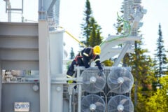
 The essentials of AC power transformers for students and beginners (on photo: Substation power transformer at the Bryce street substation in Hamilton NZ; credit: Ryan O'Connor via Flickr)
The distribution transformer normally serves as the final transition to the customer and often provides a local grounding reference. Most distribution circuits have hundreds of distribution transformers.
Distribution feeders may also have other transformers: voltage regulators, feeder step banks to interface circuits of different voltages, and grounding banks.
What does an AC transformer actually do?
A transformer efficiently converts electric power from one voltage level to another. A transformer is two sets of coils coupled together through a magnetic field. The magnetic field transfers all of the energy (except in an autotransformer). In an ideal transformer (Figure 1), the voltages on the input and the output are related by the turns ratio of the transformer:
V1 = V2 × N1 / N2
where:
- N1 and N2 are the number of turns and
- V1 and V2 are the voltage on windings 1 and 2
In a real transformer, not all of the flux couples between windings. This leakage flux creates a voltage drop between windings, so the voltage is more accurately described by:
V1 = N1 / N2 × V2 – XL × I1
where:
- XL is the leakage reactance in ohms as seen from winding 1, and
- I1 is the current out of winding 1.
The current also transforms by the turns ratio, opposite of the voltage as:
I1 = I2 × N2 / N1
A transformer has a magnetic core that can carry large magnetic fields. The cold-rolled, grain-oriented steels used in cores have permeabilities of over 1000 times that of air. The steel provides a very low-reluctance path for magnetic fields created by current through the windings.

Consider voltage applied to the primary side (source side, high-voltage side) with no load on the secondary side (load side, low-voltage side). The winding draws exciting current from the system that sets up a sinusoidal magnetic field in the core. The flux in turn creates a back emf in the coil that limits the current drawn into the transformer.
…and when we add the load to the secondary
A transformer with no load on the secondary draws very little current, just the exciting current, which is normally less than 0.5% of the transformer’s full-load current. On the unloaded secondary, the sinusoidal flux creates an open-circuit voltage equal to the primary-side voltage times the turns ratio.
The magnetic coupling of the secondary current pulls current through the primary winding, keeping constant ampere-turns. Normally in an inductive circuit, higher current creates more flux, but not in a transformer (except for the leakage flux).
The increasing force from current in one winding is countered by the decreasing force from current through the other winding (see Figure 2).
The flux in the core on a loaded transformer is the same as that on an unloaded transformer, even though the current is much higher.
The voltage on the primary winding determines the flux in the transformer (the flux is proportional to the time integral of voltage). The flux in the core determines the voltage on the output-side of the transformer (the voltage is proportional to the time derivative of the flux).
Figure 3 shows models with the significant impedances in a transformer. The detailed model shows the series impedances, the resistances and the reactances. The series resistance is mainly the resistance of the wires in each winding. The series reactance is the leakage impedance. The shunt branch is the magnetizing branch, current that flows to magnetize the core.

Power Losses
Generally speaking, power in transformer is lost in the core through the hysteresis and eddy currents. Keep in mind that hysteresis and eddy currents always occur together.
Hysteresis
As the magnetic dipoles change direction, the core heats up from the friction of the molecules. More about hysteresis and how to reduce these losses read in this technical article.

Eddy currents
Eddy currents in the core material cause resistive losses. The core flux induces the eddy currents tending to oppose the change in flux density. The magnetizing branch impedance is normally above 5,000% on a transformer’s base, so we can neglect it in many cases.
The various parameters of power transformers scale with size differently as summarized in Table 1 below:
TABLE 1 – Common scaling ratios in power transformers
| Quantity | Relative to kVA | Relative to a Reference Dimension, l |
| Rating | kVA | l4 |
| Weight | K kVA¾ | K l3 |
| Cost | K kVA¾ | K (% Total Loss)-3 |
| Length | K kVA¼ | K l |
| Width | K kVA¼ | K l |
| Height | K kVA¼ | K l |
| Total losses | K kVA¾ | K l3 |
| No-load losses | K kVA¾ | K l3 |
| Exciting current | K kVA¾ | K l3 |
| % Total loss | K kVA-¼ | K l-1 |
| % No-load loss | K kVA-¼ | K l-1 |
| % Exciting loss | K kVA-¼ | K l-1 |
| % R | K kVA-¼ | K l-1 |
| % X | K kVA¼ | K l |
| Volts / turn | K kVA¼ | K l2 |
The simplified transformer model in Figure 3 with series resistance and reactance is sufficient for most calculations including load flows, short circuit calculations, motor starting, or unbalance.
Small distribution transformers have low leakage reactances, some less than 1% on the transformer rating, and X/R ratios of 0.5 to 5. Larger power transformers used in distribution substations have higher impedances, usually on the order of 7 to 10% with X/R ratios between 10 and 40.
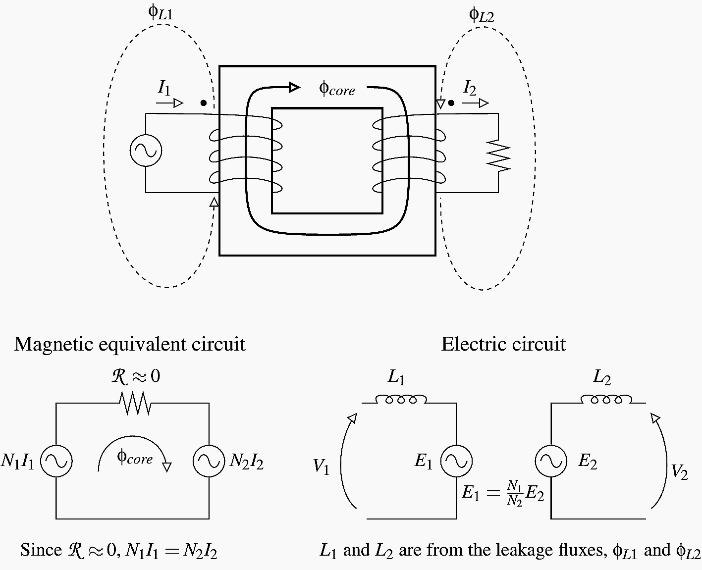
The leakage reactance causes voltage drop on a loaded transformer. The voltage is from flux that doesn’t couple from the primary to the secondary winding. Blume et al. (1951) describes leakage reactance well. In a real transformer, the windings are wound around a core. The high and low voltage windings are adjacent to each other.

Figure 5 shows a configuration. Each winding contains a number of turns of wire. The sum of the current in each wire of the high-voltage winding equals the sum of the currents in the low-voltage winding (N1I1 = N2I2), so each winding is equivalent to a busbar.
Each busbar carries equal current, but in opposite directions. The opposing currents create flux in the gap between the windings (this is called leakage flux).
The leakage reactance in percent is based on the coil parameters and separations as follows:
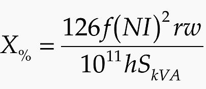
where
- f – system frequency [Hz]
- N – number of turns on one winding
- I – full load current on the winding [A]
- r – radius to the windings [in]
- w – width between windings [in]
- h – height of the windings [in]
- SkVA – transformer rating [kVA]
In general, leakage impedance increases with:
- Higher primary voltage (thicker insulation between windings)
- kVA rating
- Larger core (larger diameter leads to more area enclosed)
Leakage impedances are under control of the designer, and companies will make power transformers for utilities with customized impedances. Large distribution substation transformers often need high leakage impedance to control fault currents, some as high as 30% on the base rating.
Mineral oil
Mineral oil fills most distribution and substation power transformers. The oil provides two critical functions: conducting heat and insulation. Because the oil is a good heat conductor, an oil-filled transformer has more load-carrying capability than a dry-type transformer.
Since it provides good electrical insulation, clearances in an oil-filled transformer are smaller than a dry-type transformer.
The oil conducts heat away from the coils into the larger thermal mass of the surrounding oil and to the transformer tank to be dissipated into the surrounding environment. Oil can operate continuously at high temperatures, with a normal operating temperature of 105°C. It is flammable.
The flash point is 150°C, and the fire point is 180°C. Oil has high dielectric strength, 220 kV/in. (86.6 kV/cm), and evens out voltage stresses since the dielectric constant of oil is about 2.2, which is close to that of the insulation. The oil also coats and protects the coils and cores and other metal surfaces from corrosion.
How does a Transformer work?
This video gives a detailed animated illustration on the working of power transformers. Here the basic working principle and construction of transformer, step-up transformer, step-down transformer, transformer winding and core construction are well illustrated.
Enjoy :)
Reference // Understanding Electric Power Systems By Jack Casazza and Frank Delea (get it from Amazon)
Related electrical guides & articles


Edvard Csanyi
Hi, I'm an electrical engineer, programmer and founder of EEP - Electrical Engineering Portal. I worked twelve years at Schneider Electric in the position of technical support for low- and medium-voltage projects and the design of busbar trunking systems.I'm highly specialized in the design of LV/MV switchgear and low-voltage, high-power busbar trunking (<6300A) in substations, commercial buildings and industry facilities. I'm also a professional in AutoCAD programming.
Profile: Edvard Csanyi

many thanks
“some as high as 30% on the base rating.”
I dont like Idea
It’s not true, in my opnion. Explain more.
Tks, good article
please sent electricalstudy material as usual use in rutine life their technical method to prevent from electric shock.
And what about the laws of the transformer?
It is necessary to explain them.
no need
i tried to get the PDF copy but isn’t working…..also for other articles same problem.