
Estimated Study Time: 33 minutes
Perfect, but with stability problems
Since the subject of this article is somewhat not-that-easy to understand, I suggest starting with the basics of the synchronous motor. In the synchronous motor, the basic magnetic field is obtained by direct current excitation rather than through the air gap from the armature, as is the case with induction motors.
 The art of achieving synchronous motor transient stability
Comparatively large air gaps are used, making practicable the manufacture, even in relatively low horse-power ratings of low-speed synchronous motors. In all low-speed ratings and in large high-speed ratings, synchronous motors are physically smaller and less costly to build than squirrel-cage induction motors of equivalent horsepower.
A synchronous motor can be applied to any load which can be successfully driven by a NEMA Design B squirrel-cage motor. However, there are certain types of loads for which the synchronous motor is especially well suited.
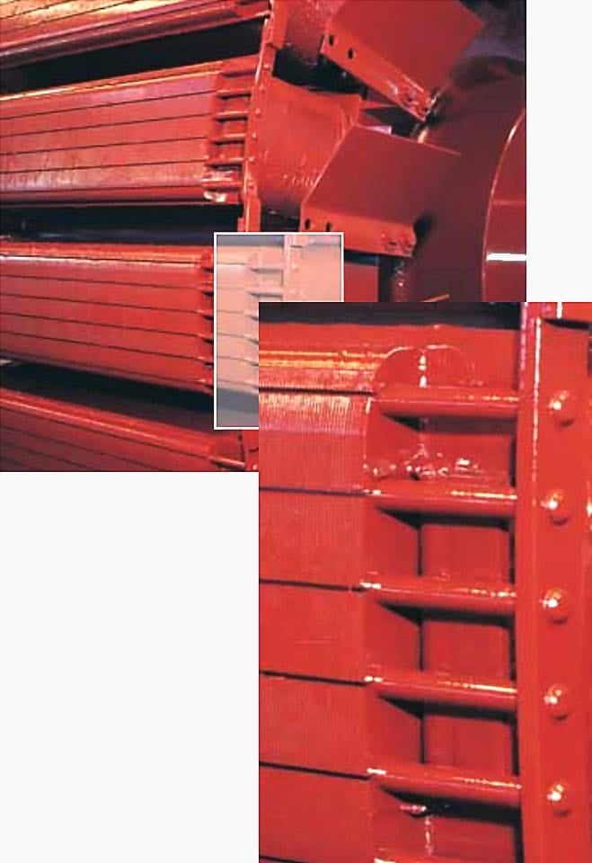
A synchronous motor consists of a frame, a stator, a rotor, an exciter, and an amortisseur winding. These components can be seen in Figure 1 below.
Figure 1 – Synchronous motor construction and main components

Apart from the synchronous motor advantages, it is prone to stability problems upon external disturbances more than the induction motor. The justification is complex, but the literature offers such an explanation extensively.
This article skims through motor starting methods, rotation directions, excitation modes, torque types, and a case study. The aim of this article is to describe the synchronous motor transient stability performance and formulate the relationship between the excitation mode and the synchronous motor stability performance.
- Synchronous Motor Method of Starting
- Synchronous Motor Rotation Direction
- Synchronous Motor Excitation Modes
- Torque Types
- Case Study of Synchronous Motor 13.2 kV, 12.8 MW at 0.9 pf
1. Synchronous Motor Method of Starting
The unexcited rotor is accelerated to the synchronous speed at which it is excited using DC source. At this moment, the rotor poles are locked into the stator poles, so they both run synchronously. The synchronous speed is given by the famous formula NS = 120 f / P.
However, the arrangement between the rotor and the stator is not absolutely rigid. If the load increases, the rotor tends to fall back in phase by a certain angle. The motor speed is constant, and the motor keeps running till the maximum load angle is reached.
Some of the commonly used methods for starting synchronous rotors are described in the following section.
Suggested Course – The Essentials of Motor Soft Starters, Motor Starting Methods and Applications
The Essentials of Motor Soft Starters, Motor Starting Methods and Applications
Go back to the Contents Table ↑
1.1 Motor Starting by Variable Frequency Drive
The rotor will be able to accelerate and lock in with the stator’s magnetic field without any difficulty if the stator’s rotating magnetic field in a synchronous motor rotates at a low enough speed. The supply frequency “f” is then gradually raised until it reaches its typical 50/60-Hz value, at which point the stator magnetic field can be accelerated to its rated operating speed.
It is now possible to continuously control the frequency of the supply connected to the synchronous motor all the way from a fraction of a hertz up to and even above the typical rated frequency thanks to the development of such modern solid-state variable frequency drive packages.
The internally generated voltage of a synchronous motor, which is typically referred to as the counter EMF, will be lower than usual when it is run at a speed lower than the rated speed. Because of this, it is necessary to decrease the terminal voltage applied to the motor in proportion to the frequency to maintain the stator current within the rated range.
It’s worth noting that any variable-frequency power supply’s voltage typically varies roughly linearly with the output frequency.
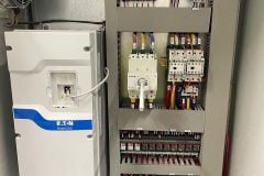
Further Study – Inside Variable Frequency Drive (VFD) Panel: Configuration, Schematics and Troubleshooting
Inside Variable Frequency Drive (VFD) Panel: Configuration, Schematics and Troubleshooting
Go back to the Contents Table ↑
1.2 Motor Starting With an External Motor
This technique involves mounting a pony motor as an external starting motor and using it to accelerate the synchronous machine toward its rated speed (though not quite to it, as the synchronization process may fail to indicate the point at which the main switch connecting the synchronous machine to the supply system closes).
The pony motor may then be removed from the machine’s shaft or the power supply to the pony motor may be cut off once the output of the synchronous machine has been synced or paralleled with its power supply system as a generator.
When the pony motor is turned off, the machine’s shaft slows down, the speed of the magnetic field in the rotor momentarily lags behind, but the synchronous machine keeps working as a motor. The synchronous motor can be loaded normally, just like any other motor, once it starts to function as a motor.
The starting motor can have a much lower rating than the synchronous motor it will start because only the motor’s inertia needs to be overcome. Typically, brushless excitation systems are mounted on the shafts of large synchronous motors. These exciters can then serve as the starting motors.
Since many medium-sized to large synchronous motors are connected to power systems that may not be able to handle the starting currents required to use the damper (or amortisseur) winding approach described next, an external starting motor or starting by using the exciter may be the only options.
Figure 2 – Phase sequence (IEC)
Go back to the Contents Table ↑
1.3 Motor Starting by Using Damper (Amortisseur) Winding
The majority of large synchronous motors are equipped with damper windings to eliminate rotor oscillations whenever the load on the synchronous machine is periodically changing. Damper windings, which resemble the bars in a squirrel cage rotor, are special bars that are inserted into grooves carved out of a synchronous machine’s pole face and then shorted out on both ends by sizable shorting rings.
Due to the presence of the damper bars, when the stator of such a synchronous machine is connected to the 3-Phase AC supply, the machine starts as a 3-Phase induction machine, much like a squirrel cage induction motor.
When the motor accelerates to a speed that is close to its synchronous speed, the DC supply to its field winding is connected, and the synchronous motor pulls into step, continuing to run at its synchronous speed.
Figure 3 – The resistance and reactance needed to generate the necessary torques are secured using a variety of bar materials and arrangements in modern amortisseur windings
Go back to the Contents Table ↑
2. Synchronous Motor Rotation Direction
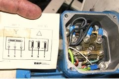
This is one of the most confusing parts of the specification stage, and it can get you in trouble. Nevertheless, it is an easy concept if dealt with caution. The stator terminals are marked with the letters U, V, and W according to IEC 60034-8 or T1, T2, and T3 according to NEMA.
Download IEC 60034-8-2014: Rotating electrical machines – Part 8 Terminal markings and direction of rotation:
Figure 2 and Figure 4 illustrate the difference between the two standards. Imagine you are standing in front of the drive end observing the motor revolving, then the rotation direction is set according to that stand (i.e., clockwise (CW) or counterclockwise (CCW)). On the other hand, NEMA views the motor rotation from the non-drive end.
Stripping, splicing, and insulating of the high-voltage cables must be performed in accordance with the instructions delivered by the cable manufacturer. The lugs should not be permanently tightened by busbars, but only attached (for checking of insulation resistance).
The cables must be supported so that no stress is applied to the busbars in the terminal box. When three-phase cables are used, the prescribed distance must be maintained between the leads at intersections. Bracing and spacers should be used if necessary.
Related electrical guides & articles


Salem Alshahrani
Electrical engineer (BEE & Meng). Specialized in substation design, especially in LV/MV switchgears and transformers. Passionate in power system planning, analysis, and stability studies.Profile: Salem Alshahrani
