
Estimated Study Time: 49 minutes
The Art of Shunt Reactor Monitoring
Nowadays, monitoring of transformers and shunt reactors is pretty much common. However, the difference is in the nuances. There are dozens of parameters that can be monitored and the the overall cost is not negligible at all. There are many benefits of monitoring the reactor operation, and the moist important is to prevent damage that could end shunt reactor life.
 Alarms Coming From the Shunt Reactor You Must Never Ignore (and What To Do) - photo credit: Elektronika Industriale sh.p.k
Monitoring vital parameters provides condition-based shunt reactor maintenance which increases reliability by detecting a problem before the shunt reactor fails. Finally. monitoring decreases repair costs.
The most important measurable indicators for oil immersed shunt reactor serviceability include:
- Top oil temperature
- Winding hottest-spot temperature
- Ambient temperature
- Fault history
- Dissolved gas analysis
The most important measurable indicators for air core shunt reactor serviceability include:
- Winding hottest-spot temperature
- Ambient temperature
- Faults history
But before we dive into details, let’s remind ourselves and our younger engineers what the sunt reactor actually is. Shunt reactors are inductive loads that are used to absorb reactive power to reduce the over voltages generated by line capacitance. An inductive load consumes reactive power versus a capacitive load generates reactive power.
Although shunt reactors are inductive loads similar to transformers but they are different than transformers in terms of construction and some electrical characteristics.
Ok, let’s dive into details.
- Thermal Overload Protection:
- Oil Temperature Protection
- Winding Temperature Protection
- Oil Level and Flow Monitoring:
- Pressure Relief Valve
- Fire Protection (Fire Extinguishing Systems):
- Checking the Integrity of Insulating Oil:
- Partial Discharge Measurements:
- Overvoltage Measurements
- Shunt Reactor Parameters that MUST be Monitored:
- Shunt Reactor Monitoring Systems
- Attachment (PDF) 🔗 Download ‘Protective Relaying Techniques and Electromagnetic Transient Analysis for Power Transformers’
1. Thermal Overload Protection
The thermal overload protection serves to prevent overheating of the shunt reactor caused by increased system voltages caused by harmonic distortions. A single overcurrent relay can carry out that function for relatively small shunt reactors, although with the drawback of neglecting the load history preceding the overload.
Consequently, employing an overcurrent relay serves merely as an approximation rather than a genuine overload protection mechanism.
The reactor is triggered only if the overload continues for an extended duration or the temperature increase nears the maximum allowable threshold.
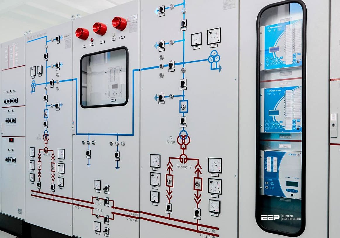
Figure 1 – Relay protection applied to high voltage shunt reactors
1.1 Heat Transfer (Thermal Process)
Heat transfer occurs in three primary components of the shunt reactor: the core, the windings, and the oil. The degree of heating of these components corresponds to their thermal time constants. The thermal time constant of a component seen as a homogeneous body can be defined by the following equation:
τ = m × c / α × S
Where:
- m = the weight of the element being considered [kg]
- c = the specific heat [Ws/kg °C]
- α = the coefficient of heat discharge by convection [W/m2 °C]
- S = the area through which the heat is discharged [m2]
The denominator of the previous formula can be substituted with the total amount of heat released per second per degree of temperature differential between the heat-dissipation surface and its environment. By implementing this replacement, the equation becomes into:
τ = m × c × θ / Qc
Where:
- Qc = the amount of heat discharged per second [W]
- θ = the temperature difference of the body and its surroundings [°C]
The temperature increase is proportional to the square of the current; so, a current of 1.26 times the rating value would increase the temperature to a final value in time T (1.2622 × 0.63 = 1), resulting in a final temperature of 1.6 times the rated value.
Figure 2 – Temperature rise as a function of time
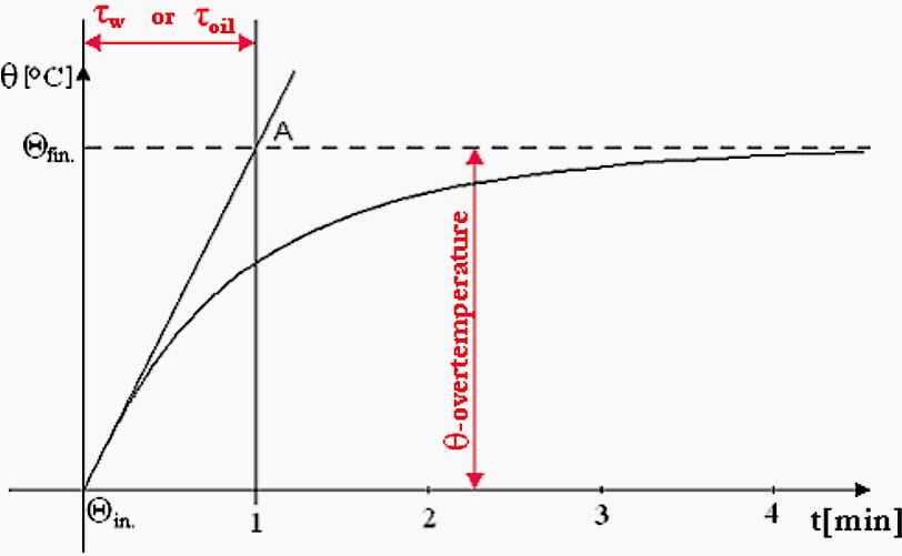
When the heat generated in the winding/core equals the heat transmitted through the oil to the tank’s surface, the over-temperature is represented by the following exponential.
θt = Θin × (1 − et/τ)
Where:
- θt = the over-temperature at time t
- Θin = the initial temperature that is stabilized by the initial load of the reactor
- τ = the time constant
Consequently, the winding temperature is the less robust component when compared to the oil and core.
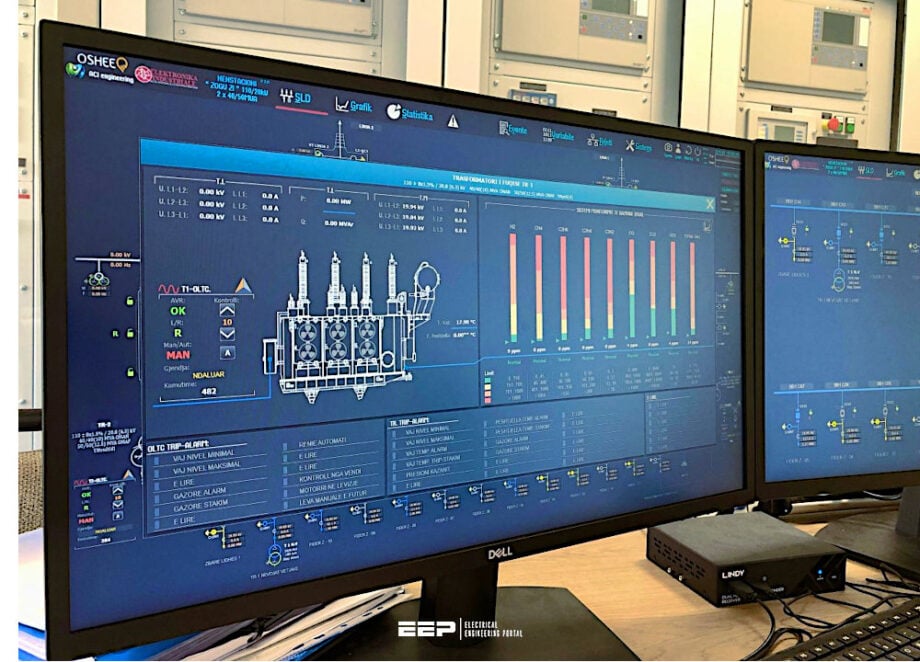
Figure 3 – Oil temperature monitoring
2. Oil Temperature Protection
In order to protect the reactor throughout its entire operating range, specialized temperature protection is necessary due to the heating and cooling requirements of an oil-immersed transmission reactor. The reactors are temperature-limited by the excitation voltage, the cooling system condition, and the ambient temperature.
The oil temperature protection is designed to prevent the insulation oil from reaching a point where the liquid properties would deteriorate or a fire would occur if its flash point was reached.
The top oil temperature is typically measured by one or two temperature sensors that are placed at the reactor cover in order to provide oil temperature protection. When a redundant temperature measurement is required, it is common to employ two sensors to ensure that the temperature protection system remains operational in the event of a sensor failure.
This is a significant advantage, as it is typically only feasible to replace a sensor after the reactor has been de-energized.
Some utilities intentionally delay the trip signal for several minutes to allow operators to take remedial actions, as oil temperature is a variable that changes slowly. These oil temperature devices do not satisfy any of the other criteria; however, they are the sole devices that satisfy the temperature limit requirements.
Figure 4 – Left: Typical Single Line Diagram (SLD) for line/bus OIR shunt reactors with associated Instrument Transformers; Right: for line/bus ACR shunt reactors
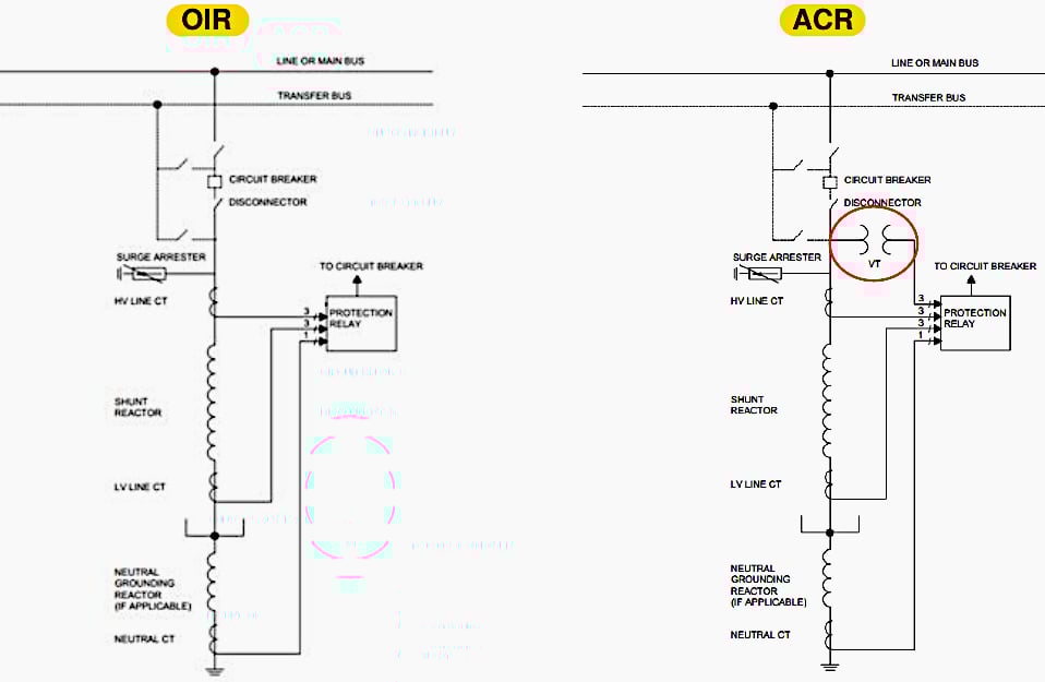
Where:
- OIR – Oil-immersed Reactors
- ACR – Air-core Reactors
3. Winding Temperature Protection
The purpose of the winding temperature protection is to prevent the solid insulation, which is usually oil-impregnated paper, from getting too hot and losing its mechanical properties too quickly (a phenomenon known as insulation aging) or even reaching bubbling temperature, which could cause a turn-turn fault by releasing water vapor bubbles.
To simulate the winding temperature, a resistor sized to approximate the heating in the reactor winding at full load is supplied by a current transformer from one of the phase currents. The resistor heating is added to the top oil temperature but circulating the top oil into a well with the resistor. This combined heating temperature is used to simulate the winding temperature.
The winding temperature usually ranges from to 140-180 degrees Celsius.
Cooling fans or oil circulation pumps, if present, are often regulated by the winding temperature relay, which operates dependent on winding temperature and/or load current.
The winding temperature protection fails to satisfy any additional requirements; yet, it remains the sole protection that complies with the temperature limit specifications.
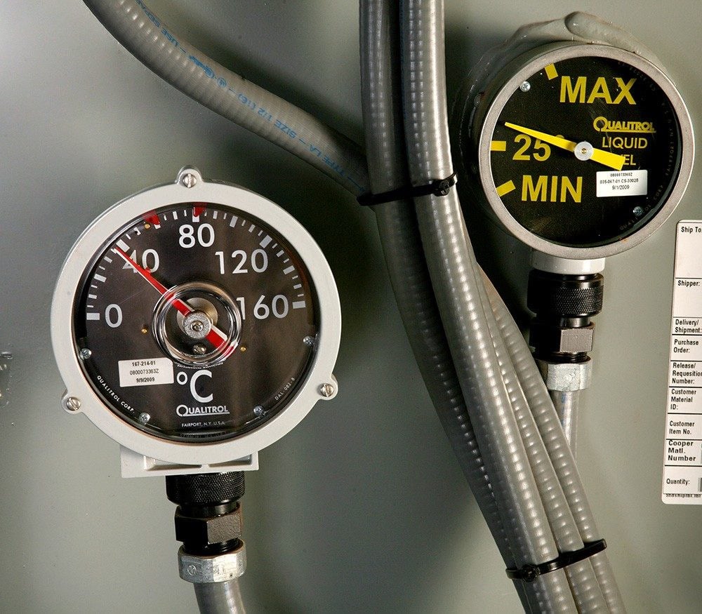
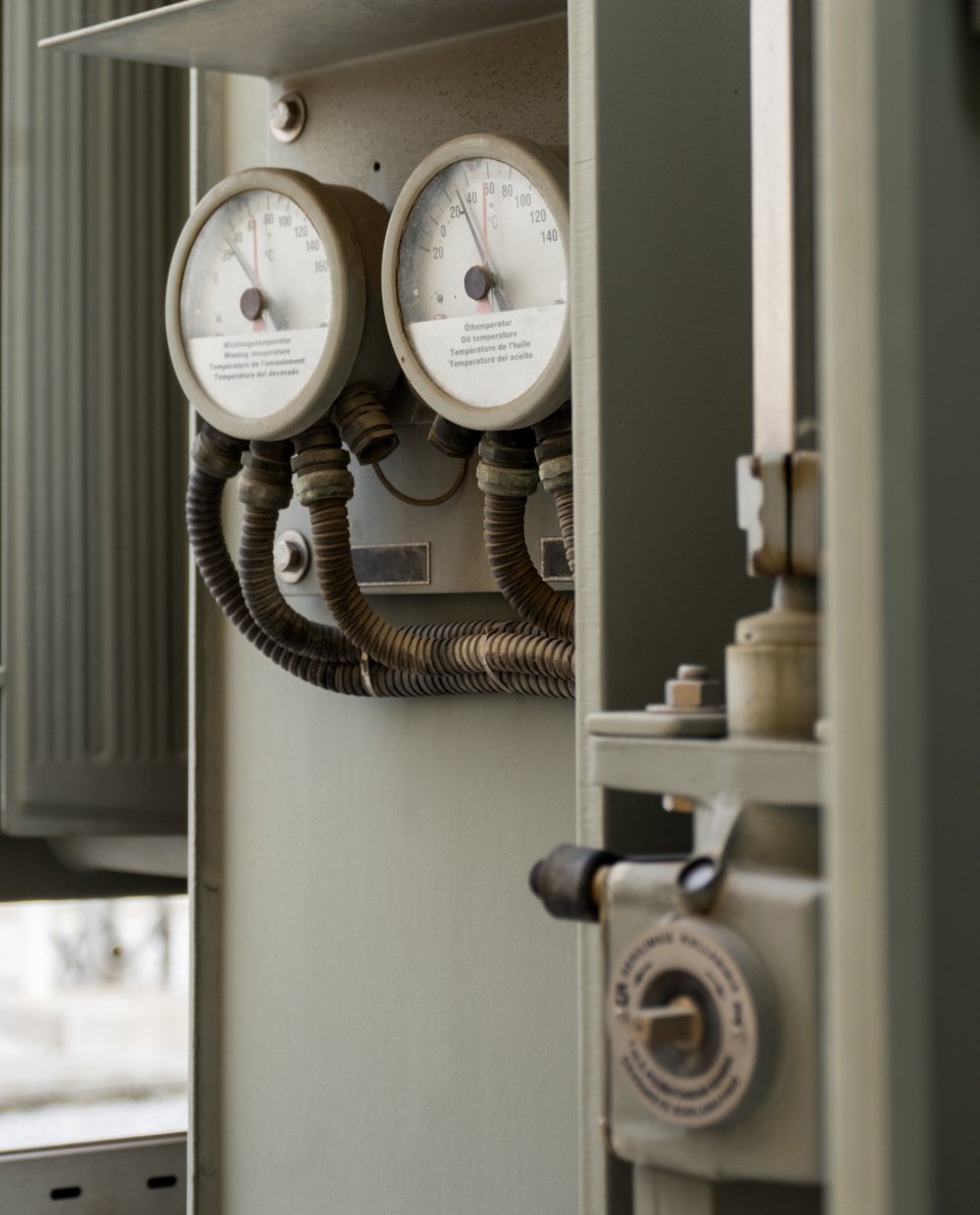
Figure 5 – Shunt reactor winding temperature and oil temperature gauges
4. Oil Level and Flow Monitoring
Oil levels in shunt reactors must be monitored in order to guarantee their operational integrity is maintained. This section outlines the devices employed for this purpose.
4.1 Magnetic Oil Level Gauge
Many shunt reactors have an expansion vessel, known as a conservator, to handle oil volume expansion brought on by temperature changes as the transformer load or ambient temperature rises. It is necessary to sustain the oil level in the conservator over a specified minimal threshold.
Consequently, all shunt reactors equipped with conservator tanks are installed with magnetic oil level gauges that include mercury switches; these switches activate audio alarms in the control room when the oil level approaches a near-empty state in the conservator.
Typically, prismatic or toughened glass gauges are being used for oil level indication.
The measured distance is transformed into a distance-proportional current signal and analyzed by the monitoring system.
Watch Video – Oil level indicator, MOG (Magnetic Oil Gauge)
4.2 Bushing Oil Level Indicator
Prismatic and toughened glass gauges are utilized for oil level indication in shunt reactor bushings.
4.3 Flow Indicators
Flow indications are installed in the oil forced air forced (OFAF) shunt reactor. These indicators are safety mechanisms that generate an electrical signal upon the failure of forced oil circulation in the cooling circuits. These flow indicators display a designated full flow rate in a given direction inside a recognized pipe size and activate one or two micro-switches when the flow rate decreases to about 70% of the designated full flow rate.
These switches can activate preventative systems or safety measures.
Related electrical guides & articles


Edvard Csanyi
Hi, I'm an electrical engineer, programmer and founder of EEP - Electrical Engineering Portal. I worked twelve years at Schneider Electric in the position of technical support for low- and medium-voltage projects and the design of busbar trunking systems.I'm highly specialized in the design of LV/MV switchgear and low-voltage, high-power busbar trunking (<6300A) in substations, commercial buildings and industry facilities. I'm also a professional in AutoCAD programming.
Profile: Edvard Csanyi
