
Estimated Study Time: 5 minutes
When fault currents can flow in more than one direction…
When fault currents can flow in more than one direction with respect to the load current it is often desirable to determine which direction the fault current is flowing and trip the appropriate devices accordingly. This is usually due to the need to de-energize only those parts of the power system that must be de-energized to contain a given fault.
Standard overcurrent relays cannot distinguish the direction of the current flow. Directional relays (67, 67N) are required to perform this function.
An important concept in the application of directional overcurrent relays is polarization. Polarization is the method used by the relay to determine the direction of current flow. For phase directional overcurrent relays, this is accomplished by the use of voltage transformers, which provide a voltage signal to the relay and allow it to distinguish the current direction.
The details of polarization methods are not discussed here.
Because the voltage on a faulted phase can be unreliable, each phase is restrained via the voltage from a different phase. Care must be used when defining CT polarities as each manufacturer typically defines a preferred polarity to match the their standard connection diagrams.
Polarization for a 67N relay is more difficult. They must be polarized with zero-sequence current or zero-sequence voltage. Electromechanical 67N relays must be polarized via either a CT in the source transformer neutral (zero-sequence current polarization) or three VT’s connected with a wye-connected primaries and broken-delta connected secondaries.

Solid-state 67N relays usually must be polarized the same way but do sometimes offer a choice of either method. Microprocessor-based relays typically offer a choice of either method and, in some cases, can self-polarize by calculating the zero-sequence voltage from the measured three-phase line voltage.
An Example
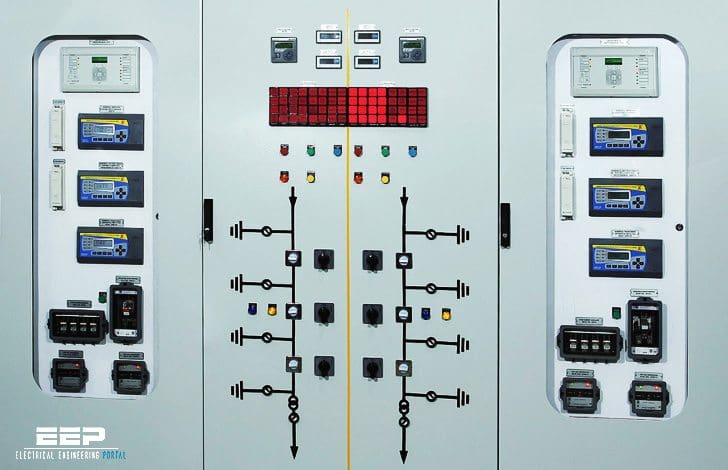
As an example of the effectiveness of directional overcurrent relays, consider the primary-selective system arrangement. The primary main and tie circuit breakers and an example of protective relaying for those circuit breakers are shown in Figure 1 below.

In Figure 1 the bus tie circuit breaker is normally-closed, paralleling the two utility feeds. Each main circuit breaker and the bus tie circuit breaker are protected via 51 and 51N relays. The mains also have 67 and 67N relays. Note that the 67 relays are polarized via the line voltage transformers, and auxiliary voltage transformers connected in wye-broken delta are supplied for polarization of the 67N relays.
The need for the 67 and 67N relays can be demonstrated by considering a fault on one of the utility feeds. Should utility feed #2, for example, experience a fault, the fault current will be supplied both from the upstream system feeding utility feed #2 and from utility feed #1 through circuit breakers 52-M1, 52-T, and 52-M2. Because the 51 and 51N relays for 52-M1 and 52-M2 are likely set identically, they will both respond to the fault at the same time, tripping 52-M1 and 52-M2 and de-energizing the entire downstream system.
To avoid this, the 67 and 67N relays are set to coordinate with the 51 and 51N relays, respectively, so that the 67 and 67N relays trip first.
For a fault on utility feed #2, the 67 and 67N relays for 52-M1 will not trip due to the fact that the current is flowing in the direction opposite to the tripping direction.
However, the 67 and 67N relays on 52-M2 will sense current in the tripping direction and trip 52-M2. The downstream system is still energized by 52-M1 and 52-T after 52-M2 trips.
Reference: System Protection – Bill Brown, P.E., Square D Engineering Services
Related electrical guides & articles


Edvard Csanyi
Hi, I'm an electrical engineer, programmer and founder of EEP - Electrical Engineering Portal. I worked twelve years at Schneider Electric in the position of technical support for low- and medium-voltage projects and the design of busbar trunking systems.I'm highly specialized in the design of LV/MV switchgear and low-voltage, high-power busbar trunking (<6300A) in substations, commercial buildings and industry facilities. I'm also a professional in AutoCAD programming.
Profile: Edvard Csanyi

How would a 67 react/operate on a loss of its polarizing voltage?
Very informative, thank you.
I had a doubt about polarization what is related to the system with polarization and without polarization.and also phasor diagram angles with RCA
This article is very useful. text is very fluent and simple for learning this subject.
Hello,
can any one explain me about the voltage reference for 67 relay with polarized and without polarized?
really good article
what is the difference between power frequency withstand voltage and lighting impulse withstand voltage?
During a lightning impulse, the stress on the insulation is short. Typically with a front time of 1.2 microsecond and a time to half of 50 microseconds. During power frequency overvoltages, the insulation is continuously stressed by a 50 Hz overvoltage, typically for 1 minute. The insulation material has better withstand against short overvoltages, such as LI.
What is the difference between directional & nan directional over current/earth fault relay
In a nutshell:
Non directional overcurrent protection, I>, can selectively protect radial networks. Selectivity achieved by introducing a time delay of operation at every relay.
Directional overcurrent protection Idir>, can selectively protect networks fed from both sides.
Thanks for your guidance for 50 67
Hi,
I am always having confusion about earth directional fault. on what behalf the polarization is selected in different relays and how to test this protection.
Please suggest me its basic. (my mail id is [email protected])
Thankyou
Hello,
How will the phasorial diagram of Voltage and Current will look for the directional relay of 52-M2 will look like in case of earth-fault upstream of 52-M2 CB ?