


Estimated Study Time: 30 minutes
Generator Protection Drawings
This article provides a comprehensive technical analysis of an 11kV generator protection relay panel +R1 designed to protect a 70MW, 3000RPM synchronous generator operating at a 0.8 power factor. The protection architecture is built upon a redundant, dual-channel philosophy utilizing Group 1 and Group 2 logic to ensure fail-safe operation and continuous availability.
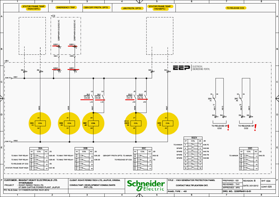 Analysis of 11kV Generator Protection Panel Drawings (PDF)
At the core of the system are two primary multi-function numerical protection relays (Main 1 and Main 2), designated in the schematics as GPRM and GPRR, which execute a comprehensive suite of ANSI/IEEE standard protection functions.
The protection scheme encompasses critical electrical and mechanical protects, including overall and stator differential protection (87G), 95% and 100% stator earth fault (64G1/64G2), and rotor earth fault (64R) facilitated by a dedicated low-frequency injection unit. The numerical relays also process complex impedance and power metrics to provide loss of excitation (40G), reverse and low forward power (32G/37G), negative phase sequence (46G), overfluxing (24G), and pole slipping (78G) protections.
Additionally, the panel integrates standard voltage and frequency protects (27G, 59G, 81G), dead machine protection (50G), and local breaker back-up/breaker failure protection (50LBB).
To execute protective actions based on the numerical relays’ logic, the panel utilizes dedicated high-speed electromechanical lockout relays segregated by specific fault zones and operational impacts. These trip executions are categorized into Unit Lockout 86A, Turbine Lockout 86B, and Generator Lockout 86C relays, all duplicated across both the Main 1 and Main 2 protection groups.
We all know that the protection panel acts as the “brain” of the generator’s electrical safety system. It continuously monitors the generator’s voltage, current, frequency, and thermal states.
When an abnormal condition (fault) occurs, the relays within this panel detect the anomaly, process the logic, and issue high-speed trip commands to isolate the generator from the grid and shut down the prime mover (turbine).
Here is the download link for the complete PDF document with drawings (56 pages). Open it up, so you can follow the discussion.
Schematics (PDF, 1.5 MB)
Ok, let’s get started!
- Physical Layout and Equipment Breakdown:
- Power System Architecture: The Single Line Diagram (SLD):
- Protective Functions and Trip Logic Architecture:
- Auxiliary AC/DC and Measurement Distribution:
- Master Lockout and Tripping Logic:
- GPRM/GPRR Input/Output and Annunciation Interfaces:
- Conclusion and Summary Notes
- Attachment (PDF) 🔗 Download Study ‘HV Shunt Reactors: Dry-Type vs. Oil-Immersed’
1. Physical Layout and Equipment Breakdown
The physical layout and component inventory of the panel are detailed across Sheets 001 through 006. Understanding the hardware is prerequisite to understanding the schematic logic.
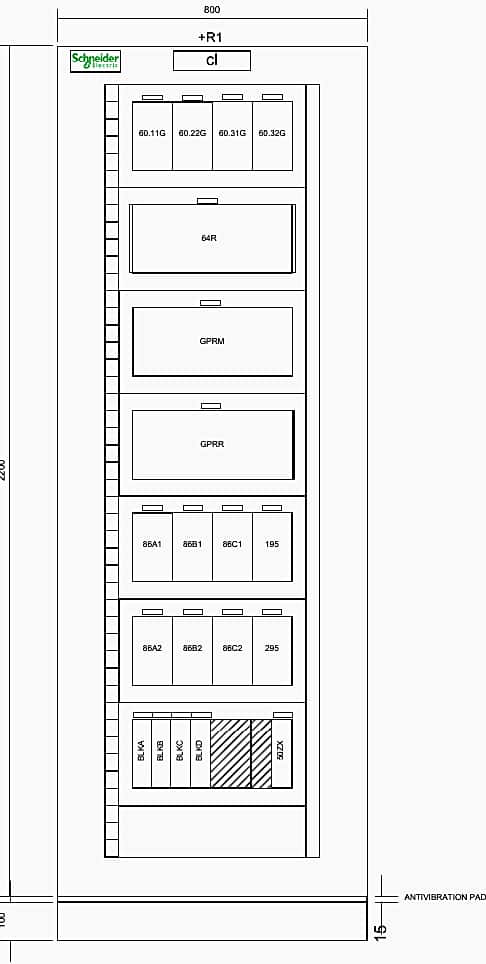
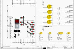
The front view of the relay panel, shown on Sheet 001 (Row C, Column 2), displays a standard 19-inch rack-style or flush-mounted layout with the main protection relays situated at eye level for easy operator access, and test blocks/trip relays located below.
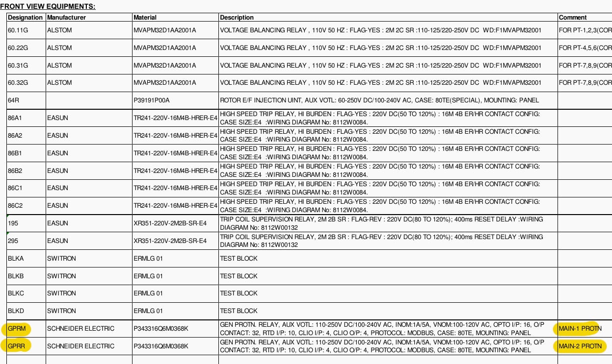
The Bill of Materials (BOM) provides specific part numbers and functions. Let us examine the primary front-view equipment listed on Sheet 002:
1.1 GPRM (Main-1 Protection Relay)
Described on Sheet 002, Row E, Column 2-8. This is a Schneider Electric MiCOM P343. It operates on a 110-250V DC auxiliary supply. It accepts nominal 1A/5A CT inputs and 100-120V AC VT inputs.
Crucially, it features 16 Opto (Digital) Inputs and 32 Output contacts, along with 10 RTD inputs and 4 CLIO (Current Loop Input/Output) ports for analog interfacing. This numerical relay acts as the primary defense line.
Figure 1 – Relay panel general arrangement
1.2 GPRR (Main-2 Protection Relay)
Described immediately below GPRM on the BOM. It is an identical MiCOM P343 relay. Utilizing two identical relays (rather than two different brands) suggests a completely redundant, parallel protection scheme where either relay can independently trip the unit.
1.3 64R (Rotor E/F Injection Unit)
Found on Sheet 002, Row B, Col 2. Since the generator rotor operates on ungrounded DC, traditional earth fault protection cannot be used. This unit injects a low-frequency AC or DC bias voltage into the rotor circuit.
If an earth fault occurs, the injected circuit completes through the fault, allowing the relay to measure the leakage current and initiate a trip.
Related Study – Trip Signal and Trip Circuit Analysis of the 132kV Line-1 (=E01) Schematics (PDF included)
Trip Signal and Trip Circuit Analysis of the 132kV Line-1 (=E01) Schematics (PDF included)
1.4 Lockout Relays (86A1, 86A2, 86B1, 86B2, 86C1, 86C2)
Listed from Sheet 002, Row C downwards. These are Easun TR241 High-Speed Trip Relays. They are high-burden relays, meaning they draw significant current momentarily to operate, making them immune to false operations from DC system ground faults or capacitive discharges.
They have 16 Make (Normally Open) and 4 Break (Normally Closed) contacts.
1.5 Trip Coil Supervision Relays (195, 295)
Easun XR351 relays. These relays constantly monitor the continuity of the Generator Circuit Breaker (GCB) trip coils. If a trip wire breaks or the coil burns out while the generator is running, the protection panel would normally be blind to this failure until it unsuccessfully tried to trip.
The XR351 prevents this by raising an alarm immediately upon continuity loss.
1.6 Voltage Balancing Relays (60.11G, 60.22G, etc.)
Alstom MVAPM32 relays. These compare the voltages between two sets of Potential Transformers (PTs). If a fuse blows on one PT, the voltage drops, creating an unbalance. The relay detects this and blocks distance or under-voltage protection elements to prevent a spurious trip.
Figure 2 – Equipment listing
2. Power System Architecture: The Single Line Diagram (SLD)
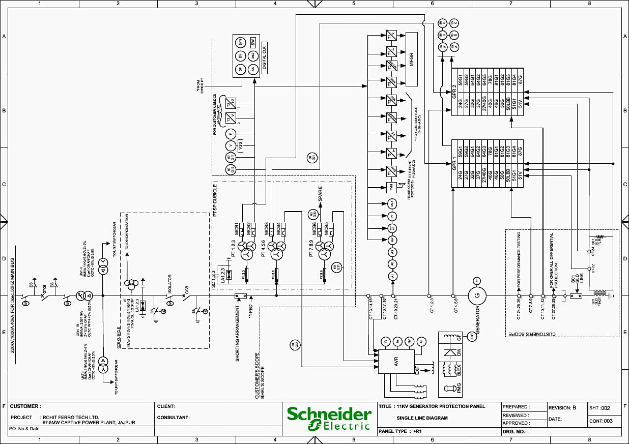
The electrical topology of the power plant is illustrated on the Single Line Diagram (SLD) across Sheets 002 and 003. This section is vital as it shows where the physical measurements (current and voltage) are taken from the primary HV equipment to feed the secondary LV relays inside the +R1 panel.
2.1 Generator and Primary Connections
On Sheet 003, Row A, Column 1, the SLD legend defines the Generator (G) as a 70MW, 11kV, 3000 RPM (indicating a 2-pole, 50Hz machine), 0.8 Power Factor synchronous generator. The generator is connected to an Isolated Phase Bus Duct (IPB) which carries the 11kV current to the Generator Circuit Breaker (GCB) shown on Sheet 002, Row C, Col 2.
From the GCB, power flows through an Isolator to the Unit Switchgear and ultimately to the 11kV/220kV Generator Transformer (GT) and into the 220kV Main Bus.
A Unit Auxiliary Transformer (UAT) is tapped directly off the 11kV bus between the generator and the GCB. The UAT is rated at 8MVA (11kV/6.9kV) and provides parasitic power to the plant’s auxiliary systems (pumps, fans) while the generator is running.
Figure 3 – The single-line diagram
2.2 Current Transformer (CT) Configuration
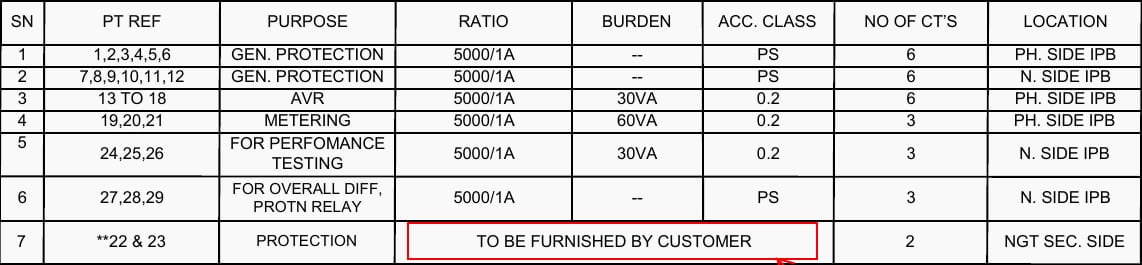
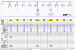
The accuracy and reliability of the protection relays depend entirely on the CTs. Sheet 003, Row D, Col 1-8 provides the CT schedule. There are several sets of CTs, all featuring a 5000/1A ratio, indicating the generator’s full load current is in the thousands of amperes.
- CT 1,2,3 (Phase Side IPB): PS (Protection Special) Class CTs used for Generator Protection. They feed the main and backup relays.
- CT 7,8,9,10,11,12 (Neutral Side IPB): These are installed on the star-point (neutral) side of the generator windings. By comparing the current at the neutral side (CT 7,8,9) with the phase side (CT 1,2,3), the GPRM/GPRR relays perform high-speed Differential Protection (ANSI 87G). If current enters the phase but does not exit the neutral, it indicates an internal stator short circuit.
- CT 13-18 (AVR): Dedicated to the Automatic Voltage Regulator.
- CT 19,20,21 (Metering): 0.2 accuracy class CTs dedicated to highly accurate revenue/panel metering (TVM – Trivector Meter).
- CT 27,28,29: PS Class CTs designated for Overall Differential Protection, which protects the entire zone encompassing the generator and the step-up transformer.
Figure 4 – Current transformers
2.3 Potential Transformer (PT) Configuration
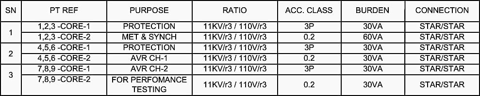
Voltage signals are derived from PTs listed on Sheet 003, Row C. The primary voltage is 11kV, stepped down to 110V (phase-to-phase) for the relays. The ratio is given as 11kV/√3 / 110V/√3, providing phase-to-neutral voltages to the panel.
- PT 1,2,3 (Core-1): 3P accuracy class, 30VA burden. Connected in Star/Star. Dedicated purely to protection circuits.
- PT 1,2,3 (Core-2): 0.2 accuracy class, 60VA burden. Dedicated to metering and synchronization.
- PT 4,5,6 & 7,8,9: Additional PTs used for redundant protection, AVR Channel 1, AVR Channel 2, and performance testing.
Useful Observation: The strict physical separation of Core 1 (Protection) and Core 2 (Metering) is a critical design mandate. Protection cores are designed to not saturate during fault currents, whereas metering cores are designed to saturate early to protect sensitive delicate meters from high voltage surges.
Figure 5 – Voltage (potential) transformers
3. Protective Functions and Trip Logic Architecture
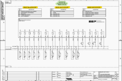
The protective philosophy of the panel is mapped out in the Trip Logic Diagrams on Sheet 004 (Group-1) and Sheet 005 (Group-2). These sheets act as Boolean logic flowcharts, illustrating how various ANSI protection functions map to specific Lockout Relays.
The segregation into Group 1 and Group 2 ensures that a failure in one lockout relay or tripping path will not disable the entire protection scheme.
Related electrical guides & articles




Edvard Csanyi
Hi, I'm an electrical engineer, programmer and founder of EEP - Electrical Engineering Portal. I worked twelve years at Schneider Electric in the position of technical support for low- and medium-voltage projects and the design of busbar trunking systems.I'm highly specialized in the design of LV/MV switchgear and low-voltage, high-power busbar trunking (<6300A) in substations, commercial buildings and industry facilities. I'm also a professional in AutoCAD programming.
Profile: Edvard Csanyi