
Estimated Study Time: 14 minutes
Defining network requirements
Before sizing an electric network, the single-line diagram of the electric network must be defined on the basis of:
 4 electric network schemes and their advantages and disadvantages (scheme credit: ABB)
- Load – it is considered fundamental to establish the true user and service requirements these are destined for, in terms of quality, availability and continuity of the power supply;
- Power supplies – It must be considered whether these are suitable or have to be integrated by resorting to other external ones, from self-production, in reserve, for emergency or for safety;
- Electric network structure – This includes selection of the diagram, machine, cable and apparatus selection and sizing of the protection and control system.
The protection system must adapt to the type of network making up the plant. In fact, depending on the types of machines and industrial process, the protection functions to be selected can be different and sometimes not homogeneous with each other.
In any case, it must be pointed out that the role of the designer who has to succeed in building a network scheme which suits the industrial process requirements is always important!
Network schemes
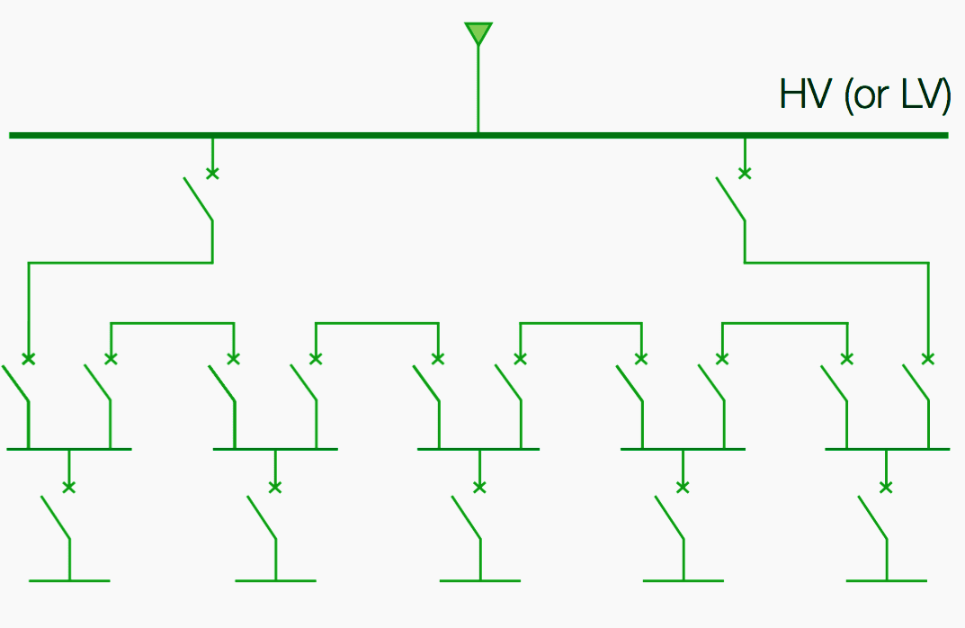
1. Single radial network
This is the simplest, least costly network scheme and the one with least overall reliability. The single radial scheme for a network with several voltage levels has a tree structure, possibly with backbones which supply the loads distributed along the route.

The main advantages of this network configuration are:
- Simplicity and
- Economy.
Vice versa, the disadvantages are:
- Maintenance (the network must be put out of service on the load side of the maintenance point);
- Vulnerability (in the case of a fault, the whole network on the load goes out of service).
2. Double radial network
The particularity of this scheme consists of having two equal alternative paths, made up by doubling a basic radial type network. Duplication of the scheme can be extended as far as the individual user, or more frequently, as far as one or more distribution nodes (busbars).
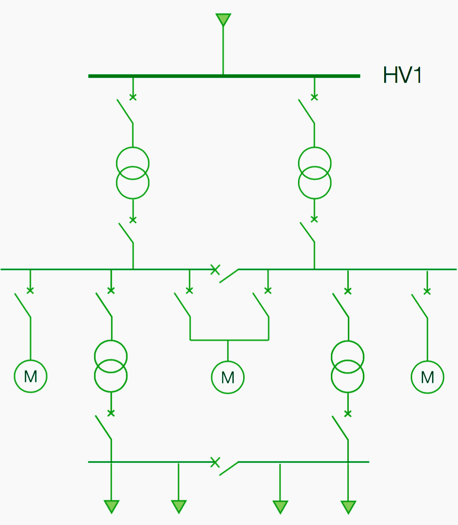
Their major use is in networks of industrial plants with process plants where a high level of service continuity is required.
The main advantages of this network configuration are:
- The limited duration of out of service in the case of a fault;
- Possibility of carrying out maintenance on parts of the plant without causing out of services or plant stoppages.
On the other hand, the disadvantage is the high costs for its realization.
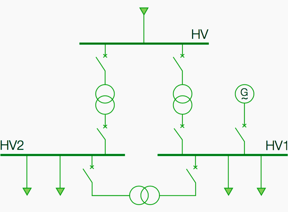
3. Ring network
Ring networks make it possible to always have two power supplies for each plant substation. In practice, the ring scheme is characterised by the presence of at least one side more (n+1) compared with the minimum needed to connect the loads to the power supply node.
Their main use is in networks where there are considerable distances between the users, characterised by small absorbed powers. In the presence of large plant loads, building a ring network can be more onerous than other types of network.
Running ring networks equipped with devices able to identify and interrupt the fault in the ring substations is, in any case, very different according to whether the ring is run open or closed.
The main advantages of ring networks equipped with protections and circuit-breakers on the in-out of each substation are:
- Service continuity, i.e. the possibility of only eliminating from service the part of the network where the fault is, keeping the remaining part of the ring in operation;
- The possibility of carrying out maintenance on parts of the plant without causing out of services or plant stoppages.
On the other hand, the disadvantages are:
- Realization costs linked to the extension of the network;
- Complexity of the protection system.
3.1 Network run with open ring
If the ring is run open, the network configuration is practically the radial type, therefore in the case of a fault the whole part of the network on the load side of the fault point will be put out of service. The disadvantages are those already been listed for single radial networks.
The advantage is being able to restore service within relatively short times, counter-supplying the substations from the sound side of the network and being able to carry out checks and repairs without the worry of production stoppage.
3.2 Network run with closed ring
Running with a closed ring makes it possible to always have two sources in parallel in every substation inside the ring and therefore, theoretically, not to have any out of services in the plant due to faults in the ring.
To identify faults in ring networks two different techniques can be used, for instance:
- Differential protections against phase faults and directional type ground protection with changeover of consent on tripping for internal faults;
- Directional overcurrent protections both against phase faults and against ground faults wired with logical selectivity.
It is necessary for there to be the pilot wires between the relays at the two ends of the line to make both the protection systems described.
The logics with which the locking signals between the protections can provided are very varied (for example, channels, either independent or not, against phase and ground faults) and additional protections can also be provided exploiting the potential logics and protection functions available in digital relays.
The “from the theoretical point of view” statement, is to underline that, from the theoretical point of view, it is possible to identify and therefore eliminate just the trunk fault from service. From the practical point of view, in many plants this is not possible since the times needed to eliminate the fault on the delivery point do not allow it.
To run ring networks, the difficulties in correctly identifying the ground faults according to the status of the network neutral and the settings of the protections defined on the supply side must be considered, particularly in the case of a ring distribution with grounded network with low fault currents.
In fact, where the setting threshold of the ground protections is a few Amperes, the risk is systematic false tripping of the protections due to problems linked with construction of the plant and which it is often not possible to eliminate.
Example //
Consider, for example, that the two outgoing feeders of the ring from the main substation are loaded with unequal currents on the three phases.

As can be seen, the total load of the ring is perfectly balanced (100 A), but the currents on the two outgoing feeders have an unbalance which can be due to various factors, such as different tightening of the cables, the non- homogeneity of the length of the single-phase cords (typical of short distances), the fact of having provided a longer cable than foreseen (then left abandoned in a substation, perhaps coiled up thereby creating a reactance), etc.
In this situation, the ground relays which read the vectorial sum of the currents by means of ring CTs, measure a current on both the outgoing feeders exactly as if there was a fault present.
When a ground fault occurs in a metallically connected network (perhaps in the network of another user connected to the same distributor line) there will be a homopolar voltage in the network and consequently the ground relays which were previously locked, are put under trip conditions when the angle returns to the foreseen sector.
In this condition, unwanted trips can occur which are not homogeneous with each other since, according to the load and position along the ring, there may or may not be unbalances with angles which are in any case variable and therefore there can be variability in tripping of the protections. In the past, this phenomenon was not noted since, there not being ring CTs, the ground fault remained in alarm (isolated neutral), or protection tripping was certain since there were high ground fault currents very far from the possible unbalances due to the plant characteristics.
In the past, this phenomenon was not noted since, there not being toroidal CTs, the earth fault remained in alarm (isolated neutral), or protection tripping was certain since there were high earth fault currents very far from the possible unbalances due to the plant characteristics.
4. Meshed network
This is the typical scheme of transmission networks and does not have any particular applications in industrial plants.
This scheme is characterised by many connections among the network nodes, to an extent to allow, for some of these, alternative power supply routes, aimed not only at establishing a reserve connection, but also to improve the load division in the various branches and among different power supply sources.
Reference // Technical guide Protection criteria for medium voltage networks by ABB
Related electrical guides & articles


Edvard Csanyi
Hi, I'm an electrical engineer, programmer and founder of EEP - Electrical Engineering Portal. I worked twelve years at Schneider Electric in the position of technical support for low- and medium-voltage projects and the design of busbar trunking systems.I'm highly specialized in the design of LV/MV switchgear and low-voltage, high-power busbar trunking (<6300A) in substations, commercial buildings and industry facilities. I'm also a professional in AutoCAD programming.
Profile: Edvard Csanyi

Am very well educated tanx
Excelente articulo sobre las configuraciones de red y las recomendaciones de protección de cada una de ellas. Saludos desde Ecuador.
realy very interesting article, thank you lot