
MV/LV transformer grounding philosophy
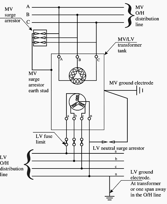
Let’s discuss in some detail the reasons for the grounding philosophy adopted for pole-mounted MV/LV transformer substations illustrated in Figure 0.
 Analysis of pole-mounted MV/LV transformer grounding (on photo: Pole-mounted distribution; credit: ee.co.za)
Contents:
- LV grounding
- MV grounding
- Combined MV/LV grounding
- Separate MV/LV grounding
- Pole transformer basics (VIDEO)
LV grounding
The purpose of LV system grounding is as follows:
- To maintain the LV neutral potential to as close to earth potential as possible thereby prospective touch voltages in all the grounded metal parts of equipment
- To provide a low-impedance return path for any LV ground faults
- To ensure operation of MV protection in the event of an inter-winding fault (MV and LV) within the transformer.
Go back to Grounding Analysis ↑
MV grounding
The surge arrestors of MV lines are connected to the transformer tank, which in turn is grounded through the MV, ground electrode. This limits the voltage between the tank and the lines to the voltage drop across the arrestors in the event of a surge.
Go back to Grounding Analysis ↑
Combined MV/LV grounding
Though it is theoretically possible to have a combined ground at the transformer for both MV and LV, such a practice may lead to unsafe conditions in the event of an MV to LV fault. Figure 1 shows the reason.
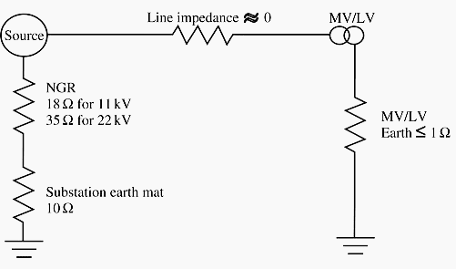
The total impedance for a fault between HV and MV winding (neglecting the line impedance and the leakage impedance of the transformer windings) is the substation ground mat resistance of 10 Ω, the NGR (neutral grounding resistance) value and the MV/LV combined ground electrode resistance assumed as 1 Ω.
IG = 12 700 / (10 + 35 + 1)
Where 35 Ω being the NGR (neutral grounding resistance) value for a 22 kV system.
This gives a figure of 276 A. This current will cause the potential of 276 V to appear on the transformer tank and through the neutral lead to the enclosures of all equipment connected in the LV system with respect to true earth potential (this is because in TN-C-S type of systems, which we saw in the last chapter, the neutral and equipment ground are one and the same).
This value is unacceptably high. In actual practice, the line and transformer impedances come into play and the value will therefore get restricted to safe values. Use of combined MV and LV grounding is therefore possible only if the ground resistance can be maintained below 1 Ω.
Go back to Grounding Analysis ↑
Separate MV/LV grounding
MV electrode
In view of the difficulty of maintaining a very low combined ground resistance arrived at above, the code allows the use of a separate ground for the LV neutral away from the transformer. The only point of connection between the LV system and the transformer tank is the LV neutral surge arrestor whose grounding lead is connected to the transformer tank (refer Figure 2 below).
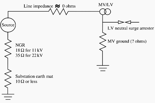
The problem with this connection is that a fault within the transformer (MV winding to core fault) resulting in rise of voltage can cause a high enough voltage to ground causing the neutral surge arrestor to fail and communicate the high voltage into the LV system.
Assuming a maximum LV voltage of 5000 V for withstand of neural surge arrestors, the voltage rise across the MV ground electrode resistance should not be greater than this value.
5000 / 12 700 = Rm / (Rm + 10 + 35)
where Rm is the resistance of MV ground electrode. It can be calculated that Rm can have a value of 29 Ωto be able to limit the voltage.
For 11 kV system, a value of 100 Ωis permissible. The limit for the electrode resistance should also consider the ground fault current so that the MV ground fault relay can operate reliably to isolate the fault. A value of 30 Ωis taken as the limit for ground electrode systems for all MV systems. Standard configurations are available in the code for 30 Ω electrodes and can be used in the design.
Go back to Grounding Analysis ↑
LV electrode
The LV electrode resistance should be normally expected to permit sufficient fault currents for detection. Since with the LV line to neutral voltage of 240 V, the resistance limit works out to 2.4 Ωif a ground fault current of 100 A is to be obtained.
However, with the TN-C-S type of system, all equipment enclosures are directly connected to the neutral at the service inlet itself and thus the current flow does not involve the ground path at all.
So, the limit of LV grounding resistance is decided by the criteria of obtaining sufficient fault current when there is an MV to LV fault without involving the tank or core (refer Figure 3).
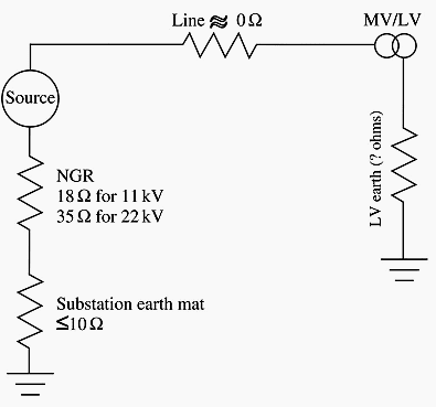
Assuming an MV earth fault protection setting of 40 A, the ground loop resistance can be arrived at 318 Ω (12 700/40) for 22 kV system. The permissible ground electrode resistance works out to 273 Ω (after taking off the values of NGR (neutral grounding resistance) and substation ground resistance).
If we consider a safety factor of 400%, the maximum value of LV ground resistance can be taken as 68 Ω. The safety factor will ensure that the seasonal changes of soil resistivity will have no adverse effect on protection operation. Standard configurations are available in the code for 70 Ω electrodes and can be used in the design.
Go back to Grounding Analysis ↑
Pole Transformer (VIDEO)
Very basic, points out components and discusses current flow.
Go back to Grounding Analysis ↑
Reference: Practical Grounding, Bonding, Shielding and Surge Protection G. Vijayaraghavan, Mark Brown and Malcolm Barnes (Buy hardcopy from Amazon)


Thank you
Hi Edvard Csanyi, i would like to know what will happen if the MV surge arrestors stud on a 22kV/400V transformer are not installed?
Hi Edvard Csanyi, Figure 0 is the standard grounding of MV/LV transformer. I would like to know what are the risks of not installing the MV surge arrestors on a 22kV/400V transformer?
In Figure 3,when there is an MV to LV fault,potential rise of the LV neutral would be
40A * 70 Ω = 2800V.
Much higher than In Figure 1.
The article presents a good amount of detailed information on the grounding of three phase pole type transformers that are used in the European type of distribution (3 wire primary, delta-wye connection, 400/230 V secondary, etc.). Yet the video was based on the North American style of distribution (single-phase transformers, 120/240 V secondary). The three phase transformers used in North America are typically connected grounded-wye grounded-wye.
Don’t get me wrong. I enjoyed reading and watching it but I think you need to tell the reader that the two segments are for two different systems or present two different articles.
Keep up the good work!
Dan Ward
Dominion Virginia Power