
Estimated Study Time: 30 minutes
Latch, Step and Lockout Relays
To be honest, expertise in relay systems is fundamental for comprehension and creativity in circuits design. From bi-stable relays that maintain their states without continuous power to step relays facilitating incremental changes, and lockout relays guarding against unauthorized reenergization, each component plays a vital role in shaping the functionality and safety of electrical circuits.
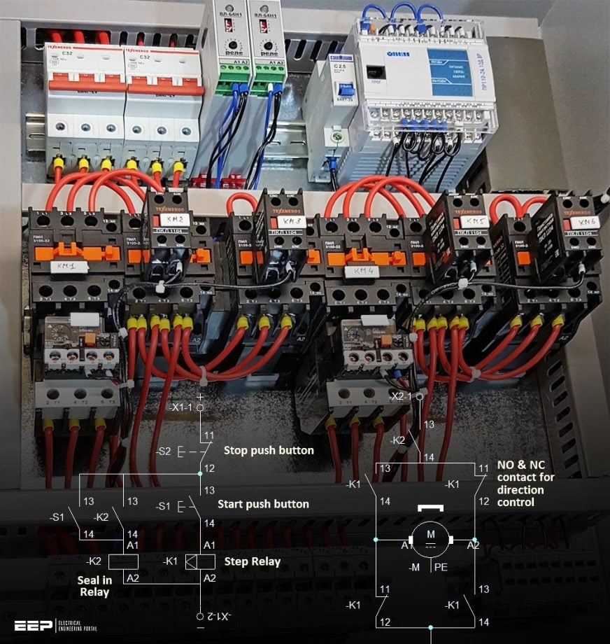 The analysis of relay control systems: Electrical schematics with latch, step and lockout relays
In previous parts of this ‘Electrical Schematics’ series, we covered many important topics, so I advise you to study those articles as well (I, II, III, IV, V, and VI).
As we embark on an exploration of these relay systems, we delve into the intricate mechanisms behind their operation and applications. The journey begins with latch or bi-stable relays, where we unravel the principles governing setting coil energization, the latch state, resetting coil activation, and the maintained state.
Through this examination, we gain insight into how these relays uphold their positions, providing stability and reliability in electrical systems.
Transitioning to step relays, we uncover their significance in facilitating controlled step-by-step movements in electrical circuits. From understanding their role in DC motor control circuits to their application in directing motor direction and operation, step relays emerge as indispensable components in automation and control systems.
As we navigate through the intricate workings and applications of latch, step, and lockout relays, we gain a deeper appreciation for their significance in the realm of electrical engineering.
Through this exploration, we aim to equip engineers, technicians, and enthusiasts with the knowledge and insights necessary to navigate the complexities of relay systems and harness their potential to drive innovation and reliability in electrical circuits.
- Latch / Bi-Stable Relay:
- Step Relay
- DC Motor Control Circuit Using Step Relay:
- Lock Out Relay or Master Trip Relay (ANSI Code 86)
- BONUS: Download Motor Circuit Design Guide (PDF)
1. Latch / Bi-Stable Relay
A latch relay, also known as a bi-stable relay, is a type of relay that differs from traditional auxiliary relays in its operation and functionality. While auxiliary relays typically have only one coil responsible for controlling the state of the contacts, a latch relay has two coils: a setting coil and a resetting coil.
The distinguishing feature of a latch relay is its ability to maintain its state even after the input power is removed. This is achieved through the use of two stable conditions, hence the term “bi-stable“. Once the contacts of a latch relay change their position due to energizing the setting coil, they remain in that position until a pulse is applied to the resetting coil.
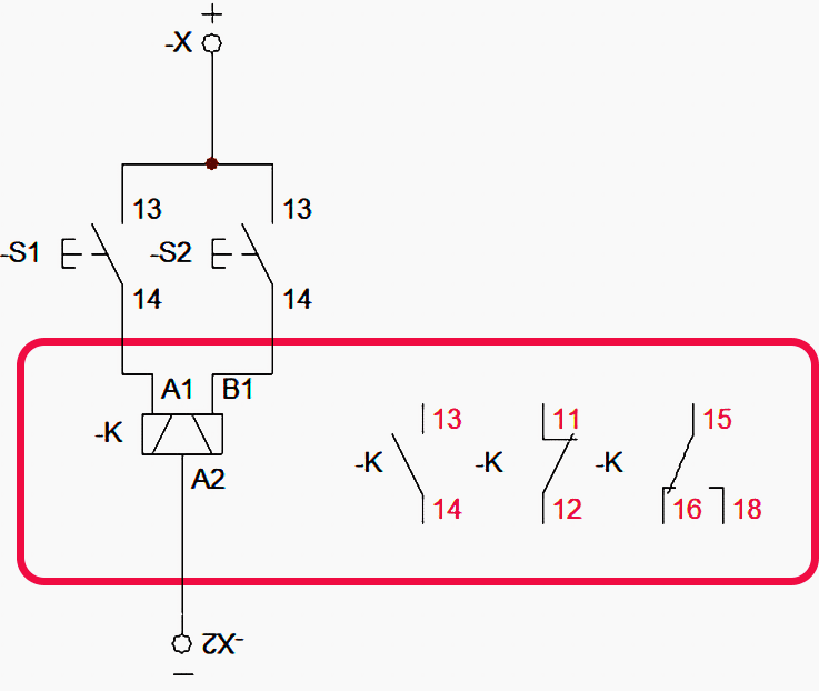
Figure 0 – Bi-stable relay (or latch relay) in electrical schematics
Here’s how the operation of a latch relay typically works:
1.1 Setting Coil Energization
When the setting coil is energized, the contacts of the latch relay change their position, either from open to closed or closed to open, depending on the design and configuration of the relay.
1.2 Latch State
Once the contacts have changed their position, they remain in that state even if the supply to the setting coil is removed. This is because the relay has effectively latched into this position, hence the name “latch relay“.
1.3 Resetting Coil Activation
To reset the contacts of the latch relay, a pulse is applied to the resetting coil. This pulse doesn’t need to be sustained; it can be just a momentary signal. Upon receiving this pulse, the relay contacts return to their original position, effectively resetting the relay.
1.4 Maintained State
Once reset, the contacts of the latch relay will remain in their new position until another pulse is applied to the setting coil to change their state again.
Latch relays find applications in various scenarios where maintaining a particular state of the contacts is desired, even in the absence of continuous power. They are commonly used in control circuits, automation systems, and other applications where a specific state needs to be maintained until intentionally changed.
In Figure 1, we are presented with an illustration of a bi-stable relay, which is distinguished by its unique characteristics and symbol. Unlike conventional auxiliary relays, the bi-stable relay features two coils, denoted by terminals A1-A2 and B1-A2.
This dual-coil configuration enables the relay to maintain its state even after the input power is removed, a feature that sets it apart from its single-coil counterparts.
Figure 1 – Normal position of bi-stable relay in the schematics
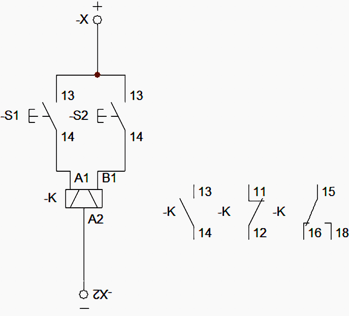
Upon closer examination of the relay symbol, we notice a subtle but significant difference from the standard auxiliary relay symbol. Two additional lines are incorporated into the symbol, indicating the presence of two coils within the relay. This visual cue serves to differentiate the bi-stable relay from other relay types and signifies its bi-stable nature, capable of maintaining two stable conditions.
Within the symbol, the relay itself, denoted as K, is depicted in its normal position. This normal position signifies the state of the relay when it is not energized or activated. The associated contacts are labeled accordingly: 13-14 represents the normally open contact, while 11-12 signifies the normally closed contact.
Additionally, we observe another set of contacts labeled as 15-16-18, which represent the changeover contact of the relay. This contact enables the relay to switch between two different electrical circuits or states, depending on the energization status of its coils.
By transitioning between these contacts, the bistable relay facilitates the desired functionality within the electrical system, providing versatility and control in various applications.
In summary, Figure 1 offers a comprehensive visual representation of a bi-stable relay, highlighting its dual-coil configuration, distinctive symbol, and key contacts. Through this illustration, we gain a deeper understanding of the relay’s structure and functionality, setting the stage for further exploration into its operation and applications in electrical circuits.
Figure 2 – Energizing the A1 coil will set the contacts
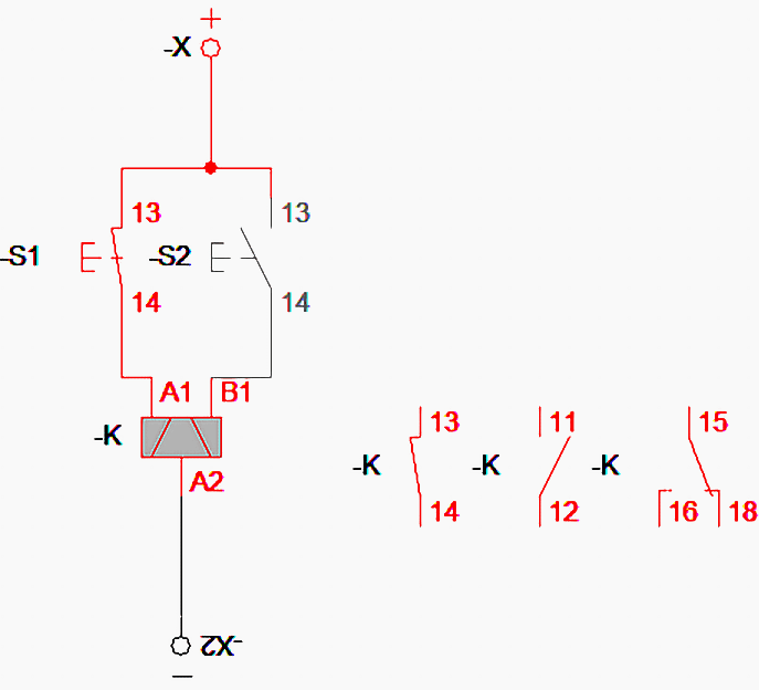
In Figure 2, we are presented with a scenario where the push button S1 is pressed, initiating the energization of the bi-stable relay coil A1-A2. As a result of this energization, several changes occur within the relay’s contacts, contributing to the alteration of the circuit’s state.
Firstly, the normally open contact 13-14 of the bi-stable relay changes its position from open to closed. This transition allows electrical current to flow through the contact, enabling the completion of a specific circuit or the activation of downstream components.
Related electrical guides & articles


Muhammad Kashif
Muhammad Kashif Shamshad is an Electrical Engineer and has more than 17 years of experience in operation & maintenance, erection, testing project management, consultancy, supervision, and commissioning of Power Plant, GIS, and AIS high voltage substations ranging up to 500 kV HVAC & ±660kV HVDC more than ten years experience is with Siemens Saudi Arabia.Profile: Muhammad Kashif
