
Estimated Study Time: 20 minutes
Introduction to Drawing Reading
The capability of reading different types of drawings is an essential skill to perform almost all of the engineering tasks. The engineering drawings form the building blocks of industry method to convey detailed information to implement, gather, troubleshoot, maintain, and run a system. Basically, the very first step to learning how to read such drawings is to become acquainted with standard procedures and basic symbols that are utilized in these drawings.
 Learn how to analyze MV switchgear wiring diagrams and single line diagram
The information contained outside the drawing areas in a print is essential to comprehend the given information in the drawing areas. The title block, revision block, grid system, notes, and legend are all examples of the non-drawing areas in the print.
Usually, the terms print, diagram, and drawing are used interchangeably to indicate the full drawing package.
Generally, engineering drawings are classified into five main areas:
- Title,
- Grid,
- Revision,
- Notes and legend, and
- Graphic
A schematic diagram is a graphical representation of system components functional formation rather than the physical formation. The schematics are categorized into three types: Single-line diagram, AC schematic diagram, and DC schematic diagram.
The detail level of these drawings falls in a spectrum in which the single-line drawing is at one end holding the least detailed and most simplified drawing type while the wiring drawing is located at the opposite end that is the most detailed and complicated type.
Substation system complexity level differs according to several factors, such as busbar arrangement, protection functions, CT/PT configurations, number of incomer/feeder circuits, and otherwise. Moreover, the CT and PT tracing and troubleshooting can be burdensome, especially for those who do not master drawing reading skills.
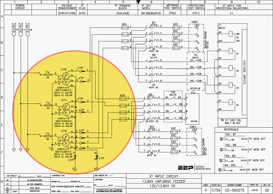
Thus, in this article, the focus is to present some tips aid analyzing MV switchgear single-line diagram and wiring diagram of measurement and protection circuits (i.e. CT & PT).
1. Single-Line Diagram
A complete single-line diagram along with the physical installment layout should be sufficient to properly plan and assess power systems. Broadly, there are two types of the single-line diagram: the system single-line diagram and the equipment single-line diagram.
The former is a general system layout that does not usually provide much detailed information, while the latter is more descriptive in terms of system capacity, control, protection, etc. The equipment single-line diagram could be for transformers, motors, busbars, feeders, or any subsystem of interest.
The single-line diagram should contain at least the following:
- Power sources in conjunction with voltage level and available short circuit current
- Conductor specifications, including size, ampacities, types, and total number
- Transformers’ ratings, capacities, impedances, voltages, vector groups, and grounding arrangement
- Protective elements quantity and type identification (i.e. fuse, breaker, and relay)
- Instrument transformers (CT & PT) ratios
- Capacitors and surge arrestors locations and types
- Loads (learn about load flow calculation and network planning)
- Any other distribution equipment
- Relay type and setting on utility source for both phase and ground faults
Details of connections and geographical locations are not important for the single-line diagram, as it needs to remain as simple as possible. After being familiar with the universally accepted single-line diagram symbols and what are the possible structure of it, one can proceed to read and understand the electric system at hand.
A single-line diagram often starts from the top of the page working its way to the bottom. It starts with utility supply or any given incomer and keeps flowing down till the load centers. Of course, one needs to pay attention to all given component details as mentioned above along the road.
It is helpful to segregate a given drawing into sections for easier analysis. For example, the main substation that has incomers delivering the bulk power from the supplier, the primary and secondary distribution, and a local generation (if any) compose one single-line diagram.

The single-line diagram might have different voltage levels that are linked by transformers, so it is important to shift focus on the transformers to see the different voltage levels in detail. For example, parallel transformers should match in impedance, voltage, vector group, and turns ratio that can be checked easily in the diagram.
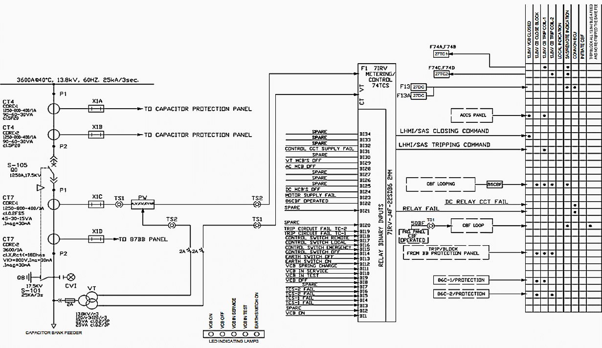
The protective components and the instrument transformers provide insight into the protection functions implemented in the system. These protection functions are numbered in accordance with ANSI/IEEE C37.2 that list specific numbering system for all protection functions in literature.
The example provided in Figure 2 lists different command signals to different cubicles within the same substation and to remote ones. These commands include close, trip, breaker failure initiation, protection functions, and otherwise.
It is prudent to view this drawing type to have a thorough picture of the system protection.
Moreover, any mechanical interlock between breakers and ground switches are to be highlighted for operational purposes. An example of the system single-line diagram is given in Figure 3 shows four major parts:
- Main substation,
- Primary distribution,
- Secondary distribution, and
- Local generation.
The utility power is transmitted at HV that is stepped down through the two identical transformers. These transformers provide power to the primary distribution to different facilities and load centers. The same principle applies to the secondary distribution and its connected loads and facilities.
Related electrical guides & articles


Salem Alshahrani
Electrical engineer (BEE & Meng). Specialized in substation design, especially in LV/MV switchgears and transformers. Passionate in power system planning, analysis, and stability studies.Profile: Salem Alshahrani
