
Estimated Study Time: 18 minutes
Reducing the arc current
Arc-suppression reactors are also named earth fault neutralisers or Petersen-coils after W. Petersen who launched the idea of this particular reactor application early in the previous century. In high voltage power systems single-phase earth faults may take place. These may be initiated by transient overvoltages, often combined with reduced dielectric strength due to contaminated insulators or the presence of animals like birds, squirrels, etc.
 How Arc suppression reactors (Earth fault neutralisers or Petersen-coils) work? - photo credit: ege.cz
Arcs arise which lead to capacitive currents. If the current is above certain levels, the arc may last for a long time and cause conductor rupture and damage to materials like insulators.
It may even cause a fire. It is generally assumed that arcs extinguish by themselves when the arc current is below 5-10 A.
In order to determine the appropriate inductance of an arc-suppression reactor, it is necessary to know the earth-fault current. This is in turn given by the capacitance to earth Ce of each phase conductor of the power system.
- Basic principle of the arc-suppression reactor
- How to determine reactor data?
- The total capacitive earth fault current
- Design of Arc-suppression reactors
- System connection
Basic principle of the arc-suppression reactor
To illustrate the effect of an arc-suppression reactor we will use an example, which is somewhat simplified but still sufficient to explain the principle.
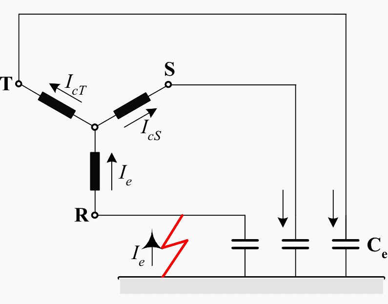
Figure 1 shows to the left an energy source that might be a secondary winding of a transformer with the terminals R, S and T.
It is connected to a system where each phase has a capacitance to earth Ce. This capacitance is distributed along the whole length of the conductors, but is indicated as one concentrated capacitor Ce per phase.
Assume that this capacitance is the same in all three phases, which means that the phase conductors of overhead lines are perfectly revolved. An earth fault is indicated in phase R.
For the sake of simplicity we assume that the impedance at the failure spot is so small that it can be neglected. In other words, the potential of phase R is equal to the earth potential, which in undisturbed and symmetrical condition lies in or close to the neutral point (star point) of the transformer winding.
Due to the earth fault the potentials to earth of phases S and T have increased. In normal operation there is an exchange of currents between the system and earth in such a way that the capacitance to earth of one phase serves as return path for the current through the capacitance of the two other phases and vice versa.
The earth fault has altered this capacitive current flow.
The vector relationships between voltages and currents are shown in Figure 2.
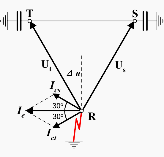
In this example the potential in relation to earth on the sound phases S and T is assumed to be equal to the normal system voltage U (line-to-line).
The capacitive currents to earth from phase S and T, Ics and Ict, are leading 90° in relation to Us and Ut respectively. The capacitive current in the earth fault Ie is the vectorial sum of Ics and Ict.
Ics = Ict = U × ω × Ce
Ie = 2 × U × ω × Ce × cos30° = √3 × ω × Ce
Depending on Ce, which is proportional to total length of lines and cables in the system, Ie may become quite high and may sustain an arc at the failure spot.
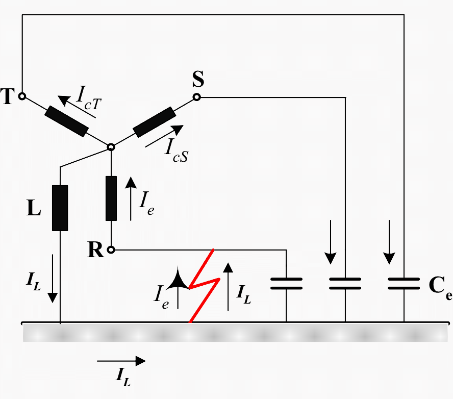
When connecting an arc-suppression reactor L between the neutral of the transformer winding and earth, an inductive current flows through L to earth where it finds its return path through the earth fault.
The inductive current through the earth fault has the opposite direction of the capacitive current provided by phases S and T.
Figure 4 shows the IL vector added to the previous vector diagram in Figure 3 before the presence of the arc-suppression reactor.

Δu is the voltage that drives the current IL through the reactor, and IL is naturally lagging 90° in relation to Δu.
By adjusting the reactance of the reactor IL can be given the same numerical value as Ie and because le and IL have opposite directions, the resulting current through the fault will become zero or close to zero.
How to determine reactor data?
The current through the reactor shall equalize the capacitive current determined by the capacitance to earth of the system where the reactor is to be installed. Then it is necessary to know Ce.
Ce can be found by direct measurement in the power system. However, the system might rarely be at disposal for such measurements, so Ce must then be estimated on the basis of calculations.
The contribution to Ce from the overhead lines might not be just as easily to determine with the same accuracy as for cables.
Ce for overhead lines is determined by several parameters such as:
- The height of the conductors above the earth
- The geometric configuration of the three phase conductors
- The number of parallel conductors per phase
- The number of earth wires, if any, and their distance to the phase conductors and to the earth
- The dimensions of the conductors
- The extent of vegetation below the line
- Seasonal variations due to ice and snow.
Exact formulas for the capacitance to earth under idealized conditions (plane earth, constant distances to earth and between conductors) are deduced in the literature (for example: R. Wilhelm and M. Waters: Neutral Grounding in High-Voltage Transmission, 1956).
Figure 5 a and b shows typical charging currents (earth fault currents) in an overhead line system as functions of the line length, with the system voltages as parameters.

The diagrams are valid for 50 Hz. For 60 Hz the currents must be increased by 20%. From these diagrams the capacitive fault current can easily be estimated.
The nominal current of an arc-suppression reactor should be the same as the capacitive fault current, which means that the reactor must be capable to carry this current for a certain time.
In addition, the reactance of the reactor must be such that it lets this current through when a certain voltage appear across the reactor.
Taking cables into account
When also cables are parts of the system, the contribution from the cables to the earth fault current must be taken into account. This should preferably be based on information from the cable suppliers, but in case such information is lacking, we provide some data as guidance.
The capacitance to earth of cables may vary within a range of 0,1 — 0,7 μF/km depending on the cable design and dimensions. We consider three different designs, which are shown in Figure 6.

The earthing capacitance for each phase Ce expressed in μF/km cable is indicated on the ordinate axis in the following Figure 7, Figure 8 and Figure 9.

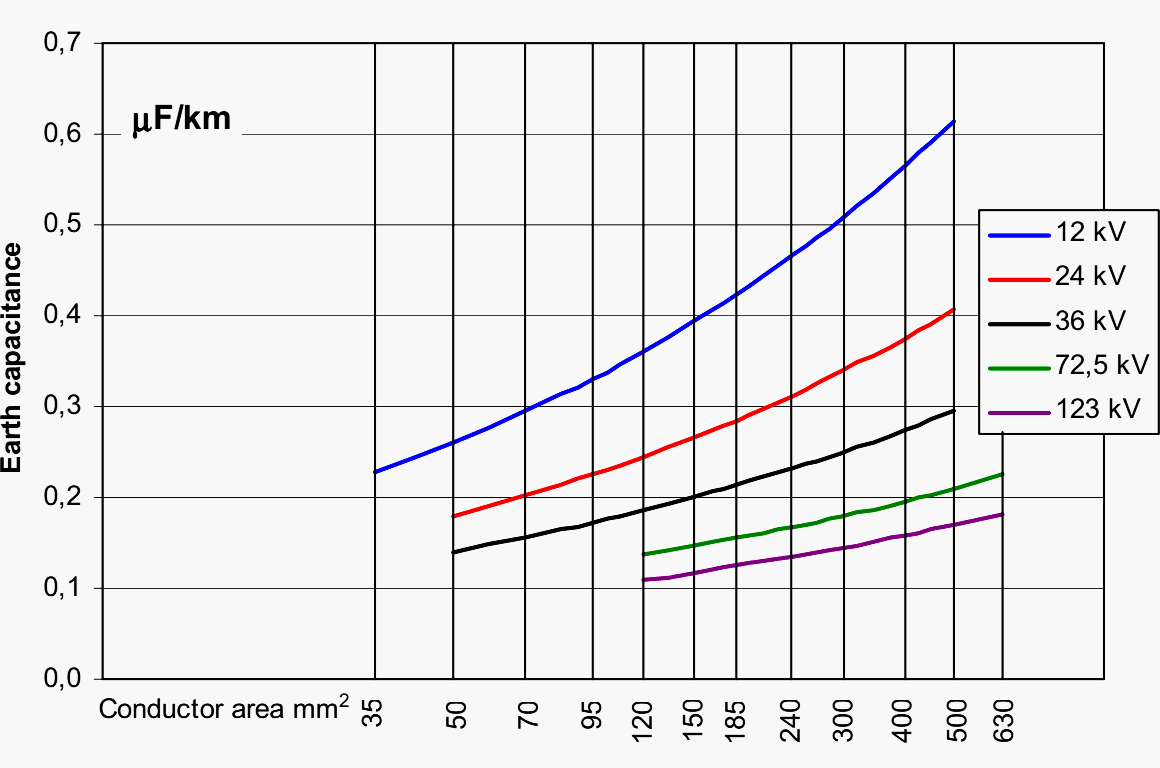
To determine the capacitive earth fault current based on the diagrams in Figures 7, 8 or 9 the ordinate Y read from the conductor area on the x-axis and the curve for the relevant system voltage should be inserted in the following formula:
Ie = √3 × 2 × π × f × Y × U × Lc × 103
In this formula:
- Ie is the capacitive earth fault current in amperes
- f is the power frequency
- Y is the ordinate from one of the diagrams in Figures 7, 8 or 9 in μF/km
- U is the system voltage (line-to-line) in kV
- Lc is the total length of the actual type of cable in the system in km.
The total capacitive earth fault current
The total capacitive earth fault current is determined by adding arithmetically the contributions from the overhead lines and from the cables.
In general the rated current of the reactor should not be too small. In case of imperfect tuning of the reactor the residual reactive current should be inductive. A capacitive residual current may cause that the voltage to earth on the healthy phases becomes still higher than the line-to-line system voltage.
Design
Arc-suppression reactors are single phase. They have a core consisting of steel sheets, just like transformer cores. In most cases the core has a centre limb, which is enclosed by the winding, and two unwound side limbs and the upper and lower yokes close the magnetic path.
The core differs from transformer cores, since the centre limb consists of a number of core steel packets with non-magnetic gaps in between.
The winding is similar to transformer windings. It may have tappings for tuning the reactance to the capacitance to earth of the system.
The reactance can be varied within a certain range. The relation between the highest and the lowest reactance is for practical reasons limited to 2,5:1. For lower system voltages (22 kV and lower) the relation can be 3:1. If larger a range is required, 10-12:1 can be achieved by regulating the gaps in the core.

Regulation of the gaps can be made by means of an electric motor. This regulation is continuous, while regulation by means of tappings in the winding is in steps.
Arc-suppression reactors are oil-immersed in most cases. Arc-suppression reactors are normally equipped with a secondary winding for indication and measurement of the voltage across the reactor.
The secondary winding is sometimes loaded with a resistance in order to increase the active component of the failure current to activate selective earth-fault relays in case of a permanent earth fault. An arc-suppression reactor does of course not remove an earth-fault when for example a conductor of an overhead line has fallen down to the earth.
However, the reactor can in such cases limit the material damages by minimising the fault current.
Normally arc-suppression reactors have a built-in current transformer for indication and measurement of the current through the reactor.
System connection
Arc-suppression reactors are connected between the power system neutral and earth. The system neutral may be available at the neutral bushing of star- or zigzag-connected transformer windings.
If a transformer with such a winding is missing at the location where installation of an arc-suppression reactor is desired, an earthing reactor (also called neutral coupler) can provide a neutral point.
To determine the reactance of the arc-suppression reactor, the zero sequence reactance of the transformer where it is connected must be known.
IEC 60076-1 Power transformers Part 1: General, defines the zero sequence impedance of a three-phase winding as the impedance, expressed in ohms per phase at rated frequency, between the line terminals of a three-phase star-connected or zigzag-connected winding, connected together, and its neutral terminal.
References //
- Transformer handbook by ABB
- Distribution Automation Handbook – Elements of power distribution systems by ABB
- Arc Supression Coils by Swedish Neutral AB
Related electrical guides & articles


Edvard Csanyi
Hi, I'm an electrical engineer, programmer and founder of EEP - Electrical Engineering Portal. I worked twelve years at Schneider Electric in the position of technical support for low- and medium-voltage projects and the design of busbar trunking systems.I'm highly specialized in the design of LV/MV switchgear and low-voltage, high-power busbar trunking (<6300A) in substations, commercial buildings and industry facilities. I'm also a professional in AutoCAD programming.
Profile: Edvard Csanyi

G-R-E-A-T! Thanks.
I would like to know the standard fault clearing time of the arc suppression coil. Thank you and possibly the price for it.
Very nice…
very explicit and easy great thast the way to teach
In final formula just above Figure 3 a Voltage is omitted. Should be:
Ie = 2 × U × ω × Ce × cos30° = √3× U × ω × Ce
Excellent article!
Pse ignore my previous email. My mistake!
Another very informative article. But the author confuses terminology when he uses the term, ‘phase’ to describe what is actually ‘line’. The capacitances described are line capacitances and not phase capacitances.