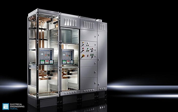
Continued from 2nd part of article: Assemblies of switchgear and control panels (part 2)
Molded case circuit breaker (MCCB)
Now coverage of distribution panels and switchboards will be presented including molded case circuit breakers (MCCB), safety switches, panelboards, multimetering equipment, ground fault circuit interrupters. Most of the codes define a circuit breaker as a device designed to open and close a circuit automatically at a predetermined overcurrent values (short circuit or o verload) without injury to itself when properly applied within its rating.
- The molded case (frame)
- Operating mechanism
- Arc extinguishers
- Contacts
- Trip elements
- The terminals (connectors i.e. mechanical / compression lugs or solid bar).
Maximum current, voltage and interrupting current determine the size and strength of the molded case circuit breaker (MCCB). Different manufacturers build breakers for the same rating with different physical sizes i.e. non-interchangeable.
The faceplate (nameplate) gives all the important data such as:
- Catalog number (reference)
- Serial number of breaker
- Interrupting ratings at different voltage classes
- Standards registration numbers i.e. for the CSA or UL
- Calibration temperature for thermal magnetic units
- Lugs data and size
- Electrical accessories
- Date of manufacturing (usually printed on back/side of circuit breaker)
These breakers are also trip free i.e. if the breaker operating handle is pushed and hold in the on position and there is a fault on the system (or the trip test button is pushed, if available) the breaker would trip open and stay open.
There are three distinct positions for the handle to settle in the ON, OFF, TRIP (which is midway between the ON and OFF positions). The breaker has to be reset after tripping by pushing the handle all the way to the OFF position and than pushing it to the ON position.
The function of the arc extinguisher is to confine, divide and extinguish the arc drawn between the breaker contacts each time the breaker interrupts. The trip element provides the protection in case of prolonged overloads or short circuits. It actuates the operating mechanism and trip the breaker open. This element is made up of electromechanical or solid state components.
The electromechanical element is referred to as the thermal magnetic and it includes:
- The bimetallic element
- The electomagnet
The current (load) flows through or heats the bimetal. When a combination of high current le vel and a long duration exists which is sufficient to deflect the bimetal far enough to physically push the trip bar and unlatch the contacts, the breaker will trip open.
There is no field adjustment available for the thermal element. The magnetic trip action is achieved through the use of an electromagnet connected in series with the load current. When the short circuit current passes through the coil this causes the electromagnet to attract the armature (trip bar) and the unlatching action causes the breaker to trip open. Magnetic trip is adjustable in 250A frame breaker and over. Two adjusting methods are availableone is the independent adjustment of each pole of the breaker thus three adjusting knobs versus one knob to adjust all poles simultaneously.
Thermal magnetic trip elements are temperature sensitive thus a modified unit to compensate for variations in ambient temperature (with a modified design) can be applied under specific conditions. An ambient compensated overload trip unit can be used whenever the breaker (protecting a cable or a down stream device) is located in a different place with different ambient temperature than the protected device or conductor, thus derating or uprating of breakers becomes unnecessary.
Ambient compensation is obtained by using an additional compensating bimetal which counter acts the effect of ambient temperature changes on the overload bimetal.
- Bus bars
- Panelboard straps
- Rear connected studs
- Plugin adapters
- Terminals (cable lugs for single or multiconductors for copper only or copper / aluminum ones).
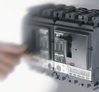
The tripping unit can be made up of solid state components or microprocessor based elements. These components replace the bimetallic and magnetic elements in a conventional molded case circuit breaker (MCCB). Internal current transformers in the breaker are required to feed in the S.S. trip unit. Each frame size can accomodate a set of rating plugs, these plugs set the rated continuous current of the breaker.
Some types of rating plugs are adjustable between 70-100% or 50-100% of the rated current of the plug itself. The breaker characteristic curves are similar to the thermal magnetic trip curves except that the different tripping actions are more clearl y defined and can be adjusted. The distinct por tions of the ch/cs curve are: the long time ampere rating & the long time delay (simulates the thermal section of a thermal magnetic circuit breaker) the short time pick up and the short time dela y (I2t in or out), the instantaneous pick up (simulates the magnetic portion in a thermal magnetic curve).
These breakers can come with a builtin ground fault protection (for solid effective grounded neutral only) with adjustment of ground fault pick up and time delay . The time current ch/cs curves for current limiting type circuit breaker have basically the same shape as conventional circuit breaker. The only difference is the current limiting action displayed at higher fault levels. A total interruption time of from 1/4 to 1/2 cycle isnconsistent with the current limiting operation.
The electromagnetic repulsion created by closely spaced parallel contact arms carrying current in opposite directions intensified by an O shaped magnet surrounding the contact arm causes the contacts to blow open in an e xtremely short period of time.
Circuits which produce high f ault currents typically are associated with low short circuit power factors (i.e. high X/R ratios). The high speed contact separation enhances the ability of the circuit breaker to limit both the peak current and the let through energy. The integral current limiting breaker is similar to the standard thermal magnetic except that it incorporates a current limiting device. This device consists of 3 current limiters specially designed to coordinate with the breaker of which they are an integral part.
All normal overloads and short circuit faults are interrupted by the thermal magnetic portion of the circuit breaker. When a large fault occurs the trigger type current limiters will blow and operate the trip bar to open the breaker, thus preventing single phasing.
The safety switches can be single throw or double throw. All switches to have visible blades and safety handles (interlock bypass lever, cross bar and operating spring).
There are two types of switch contacts the butt and the knifeblade/jaw construction. In the former, only one of the blades contact surface is held in tension against the conducting path, electromagnetic forces due to high current faults will tend to force the contacts apart therefore arcing and contact burning may be the result.
In the latter the jaws distribute a uniform clamping pressure on both sides of the blade contact surfaces, the electromagnetic forces due to the high short circuit currents will tend to squeeze the 2 sides of the jaw together onto the blade.
The action of the blade moving in and out of the jaws aids in cleaning the contact surfaces. The contacts are made of copper and the current carrying parts of the switch are plated, to reduce heating.
Fused switches will have fuse clips/holders plated and either spring reinforced or not, the classes found on these switches are J, R, or L for 800A and over . The molded case switches and the safety switches are installed in a variety of enclosures to meet practically all applications. The enclosures are designated according to Nema standards (1,3R,4,4X,5 … etc.) or CSA (1,2,3 … etc) all the enclosures have to go through a set of qualifying tests before been given such a designation.
Panelboards
Now, we shall cover panelboards. These types of boards can be classified, broadly, into two categories:
- Lighting
- Distribution / power
Another method of classification is whether the board contains breakers, switches (fused or unfused) or a combination there of.
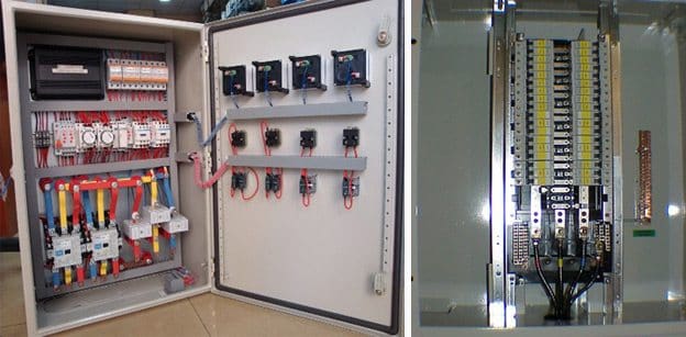
The panelboards can also be classified according to the main, accepting the incoming cable, whether it is a breaker a switch or just a set of lugs. The rating ranges, for single phase (three wire) or three phase (three or four wire) lighting panels, from 120/240V to 600V 50A 800A main breaker or main lug.
The ratings range for single phase (two or three wire) or three phase (three or four wire) power panels from 120/240V through 600V a.c. or 250V d.c., main breaker or switch or lugs, up to 1200A.
For the fusible panels the components are: the fusible switch unit, the interior assembly , the enclosure the box and the front trim parts, the cover plates (blanks)and the neutral.
There are metering equipment (centres or sockets) that are used for single phase and three phase systems. They are units that act as the point of placement for the P .U. to place its detachable meter (watthour). The single phase 120/240V, 3wire units are used in conjunction with the load centre which is located inside the single family resident.
There are three types of meter sockets:
- The non-circuit closing
- Automatic circuit closing
- The manual circuit closing
The first (non-circuit closing) means when the watthour meter is removed the service to the down stream load is interrupted, the second (automatic circuit closing) means that a mechanism to short the line to the load jaws of the socket when the meter is detached is provided, the third (manual circuit closing) offers the ability of shorting the line to the load jaws of the socket manually through the use of a slider or lever before removing the meter.
All these mechanisms are meant for temporarily shorting the socket and usually rated 50% of the continuous current carrying capacity of the socket.
The jumper bars are not to be used to make / break current. The 4 jaw meter socket is used on 120/240V a.c., 1 phase, 3 wire. The 5 jaw used with single phase loads fed from 3 phase, 4wires 120/208V a.c. system. For 3 phase, 4 wire systems the 7 jaw meter socket is used with the proper meter to measure the energy consumption of the connected loads. The type of socket trim will suit the type of socket installed.
These meter sockets can be assembled together in one lineup to meter different loads in one location like shopping centers, apartment buildings,… etc. They are built for indoor or outdoor installations.
Protection Devices
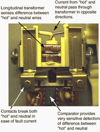
In this paragraph people protection rather than equipment protection from ground faults will be discussed. The device used is known as ground fault interrupter (GFI). The hand to hand resistance of an adult lies between 1000 to 4000 ohms function of voltage, moisture levels and muscular structure. The effect of a 60 c/s shock on a normal adult are as follows: over 5 mA painful shock, over 15ma is sufficient to cause freezing, over 30 mA causes difficulty in breathing that can lead to suffocation, 50-100 mA possible ventricular fibrillation, 100-200 mA definite ventricular fibrillation, over 200 mA severe burns & muscle contractions.
A standard overcurrent device will never sense such low levels of current despite the fact that it is dangerous to the human being. Ground fault circuit interrupters are covered in the UL standard 943 and the CSA C22.2 no. 144. The GFI should trip when the ground current reaches 6 mA or more, the time it should take to trip = [20/ground fault current].
This device should not trip below 4 mA, it also contains a means of testing the ground fault circuitry. The standards classify the GFI into class A (which is briefly covered above), portable and non classified ones. The GFI sensing components are the zero sequence current sensor that monitors the balance of the current in either the single phase 2 wire circuit (the hot and neutral wires) or the single phase 3 wire i.e. 2 pole breakers (the 2 hot and the neutral wires).
When the sensor detects an unbalance, as low as 6 mA, it will send a signal to the control circuitry. This will initiate a trip of the breaker feeding the faulty circuit (having the leakage current to ground).
The rules that govern the application and use of the GFI are given in the local applicable code, eg. CSA C22. 1.
Resource: Unknown










i am electrical all single phase & three phase enclosure control panel maker electrical company wanted please call 00971553250775
i am all electrical work technetion please companies wantes tell me mobile no 00971553250775
good seen very well