
Estimated Study Time: 28 minutes
ATS panel and circuit diagrams
One of the ways to mitigate a successive transfer of power in case of loss of supply, power outage, or scheduled maintenance is the use of a transfer switch. The transfer switch is an electrical device that transfers power from one source to another and prevents/reduces downtime. There are two main ways or methods to transfer power: manual transfer switch and automatic transfer switch.
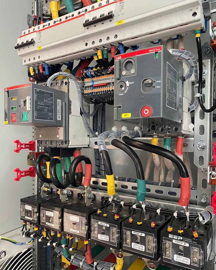 Learn what is inside the modern ATS panel and how to analyze the circuit diagrams (photo credit: АВВ Sace & ДАР-электро)
This technical article will focus on the automatic transfer switch panel by explaining how it works and discussing the main components you can spot while looking at it. In the end, we’ll make an analysis of 2600 A ATS single-line and circuit diagram.
- Automatic Transfer Switch Panel
- Components inside 2600 Amps ATS Panel
- ATS Panel Controller
- Analysis of ATS 2600 Amps Single Line Diagram
1. Automatic Transfer Switch Panel
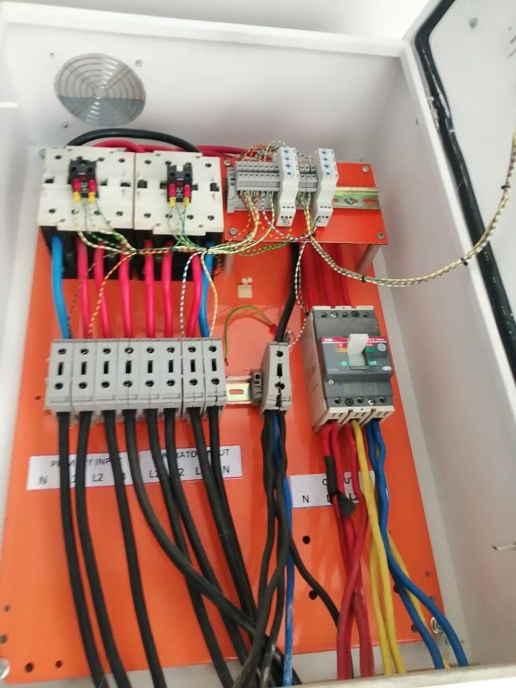
An automatic transfer switch panel is an electrical switch panel that automatically transfers supply from the primary source (grid) to the secondary source (backup) or emergency generator in the event of a power outage and retransfers power to the primary source when power is restored. ATS controller does the automatic switching by monitoring both the power grid and the backup generator.
The amperage of the ATS panel should the same as the amperage of its main breaker in the control panel.
Figure 1 – ATS Panels with contactor as a switching mechanism
Go back to the Contents Table ↑
1.1 ATS Specification and Classification
When selecting an ATS panel for a particular application, the specification is vital and plays an important role. When choosing an ATS, consider the voltage level, current carrying capacity, frequency, number of poles and phases, and short-circuit withstand capacity. You should know the class of the panels, the degree of protection, the indoor or outdoor installation, the temperature and humidity of the place.
It’s advisable to study the ratings of all components and the loads they will drive.
Go back to the Contents Table ↑
1.2 Codes and Standards
There are a few international standards that ATS Panel must conform to:
- UL 1008 – Standard to guard against transfer switch failures and resultant to a potential fire.
- IEEE 446 – IEEE Recommended practice for emergency and standby power system for commercial and industrial equipment.
- NEMA Standard ICS10 (2020) – Guide to the application of low voltage automatic transfer equipment.
Go back to the Contents Table ↑
1.3 Switching Mechanism
1. Circuit Breakers
This is a protective device used for overcurrent protection in a power system. It also functions as a disconnect switch for isolating live circuits. A circuit breaker is one of the devices that can safely switch between two sources of power to reduce downtime and outages. The switching is by mechanically interlocking the two breakers to prevent back EMF and short circuits and the ATS controller sending a signal to the breaker mechanism.
There are two types of Circuit breakers used in LV ATS panels. They are; Molded Case Circuit breakers (MCCB) and Air Circuit breakers (ACB). MCCBs are used for loads 63A to 1600A and ACBs for loads from 800A to 6300A.
Related electrical guides & articles


Chidubem Asogwa
Possess a B.Eng in Electrical and Electronics Engineering and hold a certificate of competence from Siemens Power Academy on Electrical Power systems. Expertise in Building/ Assembling, Installation, Maintenance, and commissioning of Electrical control panels and Switchgear. Currently pursuing a course on Engineering Systems Management for my Post Graduate Studies.Profile: Chidubem Asogwa
