
Estimated Study Time: 6 minutes
Fall-of-potential testing is extremely reliable, highly accurate, conforms to IEEE 81 and gives the operator complete control over the set-up. Unfortunately, it is exceedingly time consuming and labor intensive, and requires that the individual ground electrodes be disconnected from the system.
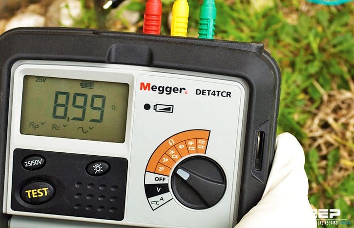 DET4TCR earth/ground resistance tester with ART - attached rod technique capability
The clamp-on testing is quick and easy, but has many limitations. It requires a good return path, is susceptible to noise, has reduced accuracies and cannot be used on isolated grounds. It is not applicable for installation checks or commissioning new sites and has no built in proof.
Attached Rod Technique (ART)
Mix of clamp-on testing and fall-of-potential testing
The Attached Rod Technique (ART) method of testing provides some of the advantages of clamp-on testing (not having to disconnect the ground electrode) while remaining true to the theory and methodology of fall-of-potential testing.
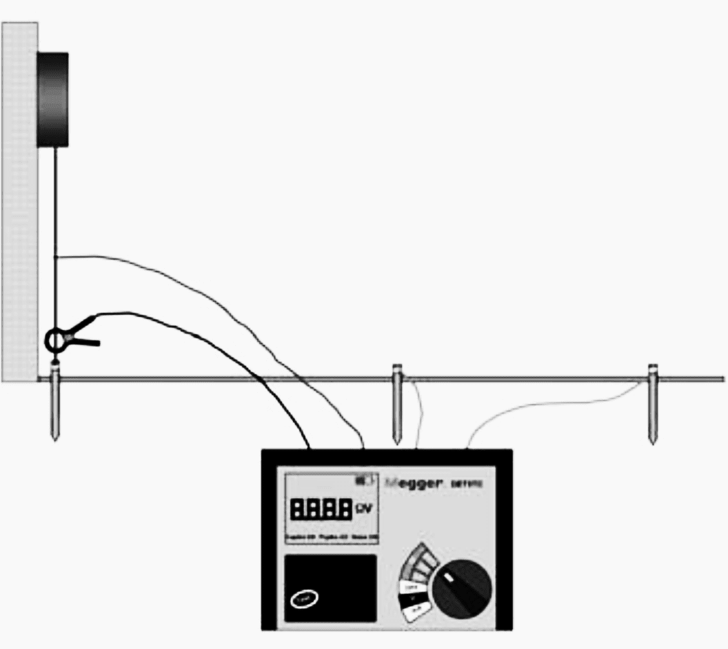
Figures 1 and 2 show the three measurements that would be made.

#1 – The first step is to measure the resistance (RT) of the entire system using a typical fall-of-potential configuration. In this example, the reading for RT is 1.9 Ω.
#2 – Step two involves measuring the total current (IT) being injected into the system from C1. For this example, IT is 9.00 mA. The next step is to measure the amount of current (IU) flowing to the service. In this case, IU is 5.00 mA.
With these measurements, the voltage drop from the selected volume of soil to the point of the P2 can be determined as follows:
- V = IT × RT
- V = 0.009 A × 1.9 Ω
- V = 0.017 V
The current through the ground electrode (IG) can also be determined as follows:
- IG = IT – IU
- IG = 9.00 mA – 5.00 mA
- IG = 4.00 mA

Using the voltage drop and the current through the ground electrode, the resistance of the ground electrode (RG) can be determined.
- RG = V / IG
- RG = 0.017 V / 0.004 A
- RG = 4.25 Ω
As noted, this is a theoretical approach that requires perfect conditions. Any additional current flowing from the service through the ground electrode would reduce the accuracy of the measurement.
The earth leakage clamp meter would have to filter out all but the current generated by the instrument through C1 to ensure accuracy. Additionally, this approach requires that a number of mathematical calculations be made.
The test is a fall-of-potential test, meaning that all the “rules” still apply. Ideally, the operator would take ten measurements and plot the results to determine true resistance. Proper probe spacing remains critical, and fall-of-potential procedure and methodology must be followed. As with a traditional fall-of-potential test, the results can be proofed by increasing the probe spacings.
The Attached Rod Technique is based on the theory outlined above. Figure 3 shows an ART test being made.
Ground testers that are designed to make ART measurements include a special built-in current clamp that is placed between the C1 connection and the earth. This type of instrument includes noise protection and digitally filters out all currents other than that generated by the instrument.
The instrument’s microprocessor automatically performs all the calculations necessary to generate a resistance measurement for the ground electrode.
The advantage of the ART method over traditional fall-of-potential testing is that the ground electrode under test does not have to be disconnected from the system.
Using ART method with Megger DET3TC to test commercial ground without disconnecting the system
Reminder! How Earth Resistivity is Measured?
A four terminal instrument is used to measure earth resistivity. Now, however, you use four small-sized electrodes driven down to the same depth and equal distances apart in a straight line. Four separate lead wires connect the electrodes to the four terminals on the instrument, as shown.
Hence, the name of this test: the four terminal method. Keep reading:
How Earth Resistivity is Measured ✔
Electrode test (VIDEO)
Reference // Getting down to earth by MEGGER
Related electrical guides & articles


Edvard Csanyi
Hi, I'm an electrical engineer, programmer and founder of EEP - Electrical Engineering Portal. I worked twelve years at Schneider Electric in the position of technical support for low- and medium-voltage projects and the design of busbar trunking systems.I'm highly specialized in the design of LV/MV switchgear and low-voltage, high-power busbar trunking (<6300A) in substations, commercial buildings and industry facilities. I'm also a professional in AutoCAD programming.
Profile: Edvard Csanyi

Interesting article, however there is an assumption in the article that to conduct a fall of potential test the earth rod (or system) being tested needs to be disconnected, this is not the case if using the off-frequency method, as commonly used in Australia/New Zealand. Using the off-frequency method the earth system is tested in it’s operational configuration i.e. as installed, and the current distribution (or splits) can be measured in all earth conductors. It is important to also measure the phase angle of the currents to determine the direction. There are test units available that can do this measurement without a reference voltage form the test set, they simply use a synchronised time signal (GPS) to measure the angle.
Off frequency testing does not require any outages or disconnections, and when completed by experienced Engineers, is just as quick as ART or 3 pole testing and yields significantly better data to assess the earthing system as a whole.
We must remember that when we conduct these tests we are not just “taking an impedance measurement” but assessing the operation of a critical safety and operational system
Regards
Andrew Hill
Specialist Engineer – Primary Design, Earthing, Lightning, EMF
Thank you for including me in this article. This this is the first one I received since left BRG on April 7th. Please let me know if you are not getting my membership fees from Paypal. Samir