
Estimated Study Time: 15 minutes
Introduction to auto-reclosing
Faults on overhead lines fall into one of three categories: transient, semi-permanent and permanent. 80-90% of faults on any overhead line network are transient in nature. The remaining 10%-20% of faults are either semi-permanent or permanent.
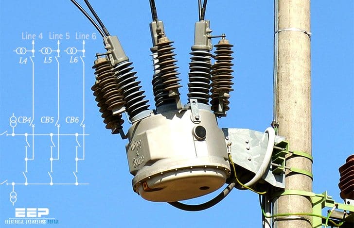 Auto-reclose schemes in HV systems for re-energise the line after a fault trip (photo credit: dribo.cz)
Transient faults are commonly caused by lightning and temporary contact with foreign objects. The immediate tripping of one or more circuit breakers clears the fault. Subsequent re-energisation of the line is usually successful.
A small tree branch falling on the line could cause a semi-permanent fault. The cause of the fault would not be removed by the immediate tripping of the circuit, but could be burnt away during a time-delayed trip. HV overhead lines in forest areas are prone to this type of fault.
Permanent faults, such as broken conductors, and faults on underground cable sections, must be located and repaired before the supply can be restored.
A further benefit, particularly to EHV systems, is the maintenance of system stability and synchronism.
Auto-reclose example schemes
Auto-reclose facilities in common use for a number of standard substation configurations are described in the following sections.
- Double Busbar Substation
- Single Switch Substation
- Four-Switch Mesh Substation
- APPENDIX:
- VIDEOs:
1. Double Busbar Substation Scheme
A typical double busbar station is illustrated in Figure 1 below. Each of the six EHV transmission lines brought into the station is under the control of a circuit breaker, CB1 to CB6 inclusive, and each transmission line can be connected either to the main or to the reserve busbars by manually operated isolators.
Bus section isolators enable sections of busbar to be isolated in the event of fault, and bus coupler breaker BC permits sections of main and reserve bars to be interconnected.
1.1 Basic scheme – banked transformers omitted
Each line circuit breaker is provided with an auto-reclose relay that recloses the appropriate circuit breakers in the event of a line fault.
The operation of either the busbar protection or a VT Buchholz relay is arranged to lock out the auto-reclosing sequence. In the event of a persistent fault on Line 1, the line circuit breakers trip and lock out after one attempt at reclosure (see APPENDIX for term ‘CB Lock-Out’).
1.2 Scheme with banked transformers
Some utilities use a variation of the basic scheme in which Transformers T1 and T2 are banked off Lines 1 and 2, as shown in Figure 1. This provides some economy in the number of circuit breakers required. The corresponding transformer circuits 1 and 2 are tee’d off Lines 1 and 2 respectively. The transformer secondaries are connected to a separate HV busbar system via circuit breakers CB1A and CB2A.
Auto-reclose facilities can be extended to cover the circuits for banked transformers where these are used.
Fault on line 1…
For example, a fault on line 1 would cause the tripping of circuit breakers CB1, CB1A and the remote line circuit breaker. When Line 1 is re-energised, either by auto-reclosure of CB1 or by the remote circuit breaker, whichever is set to reclose first, transformer T1 is also energised.
CB1A will not reclose until the appearance of transformer secondary voltage, as monitored by the secondary VT. It then recloses on to the HV busbars after a short time delay, with a synchronism check if required.
Fault on transformer T1…
In the event of a fault on transformer T1, the local and remote line circuit breakers and breaker CB1A trip to isolate the fault. Automatic opening of the motorised transformer isolator IT1 follows this. The line circuit breakers then reclose in the normal manner and circuit breaker CB1A locks out.
A shortcoming of this scheme…
A shortcoming of this scheme is that this results in healthy transformer T1 being isolated from the system. Also, isolator L1 must be opened manually before circuit breakers CB1 and CB1A, can be closed to re-establish supply to the HV busbars via the transformer.
A variant of this scheme is designed to instruct isolator L1 to open automatically following a persistent fault on Line 1 and provide a second auto-reclosure of CB1 and CB1A. The supply to Bus C is thereby restored without manual intervention.
2. Single Switch Substation
The arrangement shown in Figure 2 consists basically of two transformer feeders interconnected by a single circuit breaker 120. Each transformer therefore has an alternative source of supply in the event of loss of one or other of the feeders.
For example, a transient fault on Line 1 causes tripping of circuit breakers 120 and B1 followed by reclosure of CB 120. If the reclosure is successful, Transformer T1 is re-energised and circuit breaker B1 recloses after a short time delay.
If the line fault is persistent, 120 trips again and the motorised line isolator 103 is automatically opened. Circuit breaker 120 recloses again, followed by B1, so that both transformers T1 and T2 are then supplied from Line 2.
3. Four-Switch Mesh Substation
The mesh substation illustrated in Figure 3 is extensively used by some utilities, either in full or part. The basic mesh has a feeder at each corner, as shown at mesh corners MC2, MC3 and MC4. One or two transformers may also be banked at a mesh corner, as shown at MC1.
Mesh corner protection is required if more than one circuit is fed from a mesh corner, irrespective of the CT locations – see APPENDIX: Mesh corner protection for more details.
Considerable problems can are encountered in the application of auto-reclosing to the mesh substation. For example, circuit breakers 120 and 420 in Figure 3 are tripped out for a variety of different types of fault associated with mesh corner 1 (MC1), and each requires different treatment as far as auto-reclosing is concerned. Further variations occur if the faults are persistent.
A summary of facilities is now given, based on mesh corner MC1 to show the inclusion of banked transformers. Facilities at other corners are similar but omit the operation of equipment solely associated with the banked transformers.
Transient fault on Line 1
Tripping of circuit breakers 120, 420, G1A and G1B is followed by reclosure of 120 to give dead line charging of Line 1. Breaker 420 recloses in sequence, with a synchronism check. Breakers G1A, G1B reclose with a synchronism check if necessary.
Persistent fault on Line 1
Circuit breaker 120 trips again after the first reclosure and isolator 103 is automatically opened to isolate the faulted line. Breakers 120, 420, G1A and G1B then reclose in sequence as above.
Transformer fault (local transformer 1A)
Automatic opening of isolator 113A to isolate the faulted transformer follows tripping of circuit breakers 120, 420, G1A and G1B. Breakers 120, 420 and G1B then reclose in sequence, and breaker G1A is locked out.
Transformer fault (remote transformer)
For a remote transformer fault, an intertrip signal is received at the local station to trip breakers 120, 420, G1A and G1B and inhibit auto-reclosing until the faulted transformer has been isolated at the remote station. If the intertrip persists for 60 seconds it is assumed that the fault cannot be isolated at the remote station.
Isolator 103 is then automatically opened and circuit breakers 120, 420, G1A and G1B are reclosed in sequence.
Transient mesh corner fault
Any fault covered by the mesh corner protection zone, shown in Figure 3, results in tripping of circuit breakers 120, 420, G1A and G1B. These are then reclosed in sequence.
Persistent mesh corner fault
The sequence describe in Section 14.12.3.5 is followed initially. When CB 120 is reclosed, it will trip again due to the fault and lock out. At this point, the logic inhibits the reclosure of CB’s 420, G1A and G1B and locks out these CB’s. Line isolator 103 is automatically opened to isolate the fault from the remote station.
APPENDIX
What is the CB Lockout
If reclosure is unsuccessful the auto-reclose relay locks out the circuit breaker. Some schemes provide a lockout relay with a flag, with provision of a contact for remote alarm. The circuit breaker can then only be closed by hand. This action can be arranged to reset the auto-reclose relay element automatically.
Circuit breaker manufacturers state the maximum number of operations allowed before maintenance is required. A number of schemes provide a fault trip counting function and give a warning when the total approaches the manufacturer’s recommendation. These schemes will lock out when the total number of fault trips has reached the maximum value allowed.
Mesh Corner Protection
The protection of busbars in mesh connected substations gives rise to additional considerations in respect of CT location. A single mesh corner is shown in figure 4(a). Where only one connection to the mesh is made at a corner, CT’s located as shown will provide protection not only to the line but the corner of the mesh included between them.
Protection CT’s must therefore be located on each connection, as shown in Figure 4(b). This leaves the corner of the mesh unprotected, so additional CT’s and a relay to provide mesh-corner protection are added, as also shown in Figure 4(b).
How to Operate a Recloser? (VIDEO)
Learn how to operate a recloser both manually and using the smart control panel.
How to Install a Recloser? (VIDEO)
In Aurora, Illinois, just west of Chicago, a Commonwealth Edison crew installs a new G&W Viper ST recloser.
Reference // Network and protection automation guide by AREVA T&D
Related electrical guides & articles


Edvard Csanyi
Hi, I'm an electrical engineer, programmer and founder of EEP - Electrical Engineering Portal. I worked twelve years at Schneider Electric in the position of technical support for low- and medium-voltage projects and the design of busbar trunking systems.I'm highly specialized in the design of LV/MV switchgear and low-voltage, high-power busbar trunking (<6300A) in substations, commercial buildings and industry facilities. I'm also a professional in AutoCAD programming.
Profile: Edvard Csanyi

Dear EEP Team,
Good morning!
It’s a pleasure to connect with you. I am Jonas from Xian Xiwuer Electronic And Info. Co., Ltd.
We understand your company is a key supplier ofautomatic reclosers. Current market trends indicate that traditional recloser technology faces significant demand for upgrades—a shift driven by inherent technological evolution.
We’d like to introduce our latest capacitive power extraction automatic recloser solution:
1.Automatic recloser + capacitor voltage divider (integrated) + FTU
2.Automatic recloser + voltage transformer + FTU
Caption: Left: New capacitive powerd recloser. Right: Traditional PT-powered recloser (for reference).
Key Advantages of Our New Solution:
……
PT Elimination: Completely replaces traditional voltage transformer (PT) power supply and its inherent flaws.
Invitation toCollaborate:
Should your company explore upgrading recloser product lines to meet evolving market demands, we welcome deeper discussions. With extensive expertise in this field, we look forward to collaborating in any form that aligns with your goals.
We’re happy to provide detailed technical documentation or arrange a product demonstration at your convenience.
Thanks a lot for your reading.I am looking forward to your reply.
Best regards,
Jonas
I need an auto recloser for my 2500kv/33kva
I need it for my 2500kv/33kva