
Estimated Study Time: 18 minutes
Why bus transfer?
In order to ensure uninterrupted supply to connected loads in thermal and nuclear power stations, two types of automatic supply transfer schemes are normally used: automatic bus transfer scheme and auto-changeover scheme.
 Automatic bus transfer scheme in thermal and nuclear power stations
This technical article as explained by BHEL deals with automatic bus transfer scheme, used in medium voltage switchgear of thermal power stations, which is required for transferring load from the unit transformer bus to the station transformer bus and vice versa.
1. Automatic Bus Transfer Scheme
Automatic bus transfer schemes are normally required for switchgear employed in large thermal / nuclear power plants, where it is absolutely essential to provide uninterrupted power to the power plant auxiliaries, even during failure of their primary source of power, viz. the unit or station auxiliary transformer.
Medium voltage switchgear employed in large power plants are mainly divided into two main categories: unit switchgear and station switchgear.
1.1 Unit Switchgear
The unit switchgear receives power from the unit auxiliary transformer (UAT), which is directly connected to the output of generator of the same unit. Hence it is called a unit switchgear. It mainly supplies power to all the auxiliaries of the power plant that are essential for the running of that particular unit.
Some examples of important auxiliaries are boiler feed pump, circulating water pump, various fans, etc.
1.2 Station Switchgear
The station switchgear receives power from the station auxiliary transformer (SAT), which is fed from an outside source. This switchgear is mainly used for start-up of the power plant for power plant/township lighting and other supplies, and to feed auxiliary switchboards for coal handling, ash handling, etc., i.e. auxiliaries that are common to more than one unit.
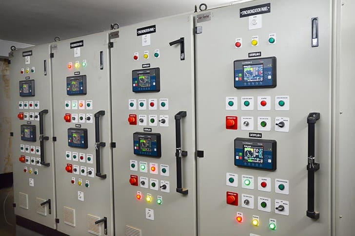
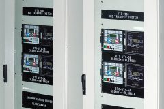
An illustration of the typical arrangement of a unit and station switchgear, and unit to station bus transfer scheme, in a power station, is given in Figure 1.

Scheme explanation
Before the power plant starts generating power, it is required to start-up the auxiliaries like the boiler feed pump, CW pump, etc. During start-up, as the unit is still not generating, the unit switchgear bus is fed from SAT through a tie connection to the station switchgear bus.
Once the unit starts generating power, the unit switchgear bus is disconnected from the station switchgear bus, and starts taking power from the unit itself, through UAT.
Hence the power supply to the unit switchgear bus is again taken from SAT, through the tie connection to the station switchgear bus.
This is called a unit to station bus transfer.
Once the fault is cleared and the unit starts generating power again, the incoming supply to the unit switchgear bus is again shifted from SAT to UAT, by opening the tie breaker between the station and unit switchgear buses, and closing the incomer from UAT.
This is called a station to unit bus transfer.
Sometimes, due to a fault in one station transformer, it may also be required to shift supply of the station switchgear from one SAT to another, through tie breakers provided between two station buses.
This is called a station to station bus transfer.
This entire operation of shifting of the power from unit to station bus and vice versa or from one station bus to another, has to be very fast and accurate. Also, care has to be taken to ensure that such a bus transfer should not take place if there is any fault on unit or station bus, or if the station supply is not available.
There are many other interlocking conditions, which govern the functioning of bus transfer. The transfer of bus can sometimes be manual and sometimes automatic, depending upon the operating conditions. All these functions are carried out through the use of special bus transfer schemes, which are explained below.
The bus transfer could be manual (pre-planned) in the event of the transfer of unit load from station to the unit transformer as is the case immediately after the unit has been started. The operation could also be vice versa.
Similarly, in the event of one station transformer being taken out for some reason, the corresponding section of the station board is fed from the other station board. The transfer could also be automatic in the event of a fault characterised by the operation of protection relay.
The manual and automatic bus transfer can be arranged in such a way that any of the following modes of operation is possible.
1.3 Modes of Bus Transfer
- Manual bus transfer:
- Without voltage interruption (allowing short parallel operation of the two sources)
- With voltage interruption
- Slow changeover
- Fast changeover
- Automatic bus transfer (under fault condition) with voltage interruption:
- Slow changeover
- Fast changeover
1.3.1.1 Manual changeover without voltage interruption (short parallel operation)
This mode of operation is not used in the normal course because it involves the paralleling, however shortly, of the station and unit transformers or of the two station transformers. Such paralleling is not permissible because it will result in the fault level rising beyond the specified withstand and rupturing the capacity of medium voltage circuit breakers.
The interlocking of the auxiliary system is so devised as not to permit, in the normal course, such a parallel operation.
However, in case of an emergency, when the other modes of bus transfer with voltage interruption are not available, this mode can be adapted with due precautions.
The bus transfer can be operable in either direction, i.e., transfer of unit load from the unit transformer to the station transformer and vice versa or transfer of the station load from one station transformer to the other station transformer.
1.3.1.2 Manual Changeover with Voltage Interruption
a) Slow Changeover
This changeover consists in switching off the existing source of supply and allowing the residual voltage of motors connected to the bus to decay sufficiently, whereafter only impulse goes to the breaker of the new source of supply for closure.
This signal for closing the new supply source breaker goes only after the residual voltage has reached the pre-set value, which is about 20% of the rated voltage.
Since the residual motor voltage has dropped down to as low a level as 20%, it pre-supposes that the motors have slowed down considerably. As such, on closure of the new sources of supply, there will be a danger of heavy inrush of starting current which will last till the motors are accelerated to the normal speed.
This starting current inrush, though somewhat lower than when starting from standstill, will yet be high enough to cause a heavy voltage drop in the transformer impedance of the new source which may be severe enough to cause the motors to pull out.
In order to safeguard against such a contingency and to make bus transfer purposeful, it is therefore essential that simultaneously with the tripping of the existing source of supply, a trip command also goes to a pre-selected number of non-essential auxiliary motors on a pre-calculated basis so that inrush current at the time of closure of the new supply will be so restricted as to limit the voltage drop to not more than 15% of the rated voltage.
This mode of bus transfer can also be available for bus transfer in either direction, i.e. from the unit transformer to the station transformer and vice versa.
b) Fast Changeover
This changeover ensures that the bus transfer takes place so rapidly that the residual motor voltage vector has fallen behind the incoming voltage vector only so little.
On one hand, closure against phase opposition is ruled out, on the other hand, at the time of the closure, the connected motor speed has dropped down only marginally with the result that at the moment of transfer of connected motors to the new source of supply, there is only a small rise of current as compared to the normal running current (this marginal rise could be of the order of 50%).
The voltage drop during the bus transfer is therefore marginal and the bus transfer is satisfactory.
This relay otherwise blocks the closing command thereby preventing the changeover under unfavourable conditions of the new source and the residual voltage of the decaying bus.
The phase comparison relay supervises the two sources continuously and is fast operating with the minimum operating time.
How phase comparison relay works?
In basic phase comparison (PC) protection, the channel does not attempt to send the entire waveform between terminals. Instead, the channel conveys only the phase information regarding the current by sending only one of two states – either the sending end waveform is above the zero axis, or it is below the axis. The same two-state logical determination is made for the local current signal at the receiving terminal.
After delaying the local signal to align with the received signal, the states of the two signals are compared (see Figure 3).
For normal load flow or for an external fault, the situation is as shown on the right. Current flows into one end, and out the other. If the CT circuits are consistently polarized at the two ends, then the local and remote mark signals (positive phase position of respective current signals) have little or no coincidence – if we combine them with an AND gate, its output will be false, or will have at most two short true pulses per power cycle if the current waves are not exactly out of phase.
For an internal fault, as shown on the left, current flows into the line from both ends. The local and remote mark signals are now aligned for all or most of the positive half-cycle. The output of the AND gate now comprises a positive or true pulse lasting about one-half cycle, alternating with a false or zero output of the same duration.
If the AND gate output feeds a timer of about one quarter power cycle pickup delay, the output can be used to initiate tripping of the local breaker.
1.3.2 Automatic Changeover with Voltage Interruption, under Fault Condition (Fast Changeover followed by Slow Changeover)
As compared to the bus transfer described above, the changeover in this mode of transfer is initiated automatically on sensing a fault to the existing voltage supply. Thus with the help of appropriate sensing relays, the bus transfer takes place automatically when the existing voltage drops below a certain voltage level for a pre-set time (about 85% of the rated voltages).
This mode of bus transfer can be available for bus transfer from the unit transformer to the station transformer.
References //
- Switchgears book by BHEL – Bharat Heavy Electricals Limited
- Phase Comparison Relaying by Bogdan Kasztenny, Ilia Voloh (General Electric) and Eric A. Udren (KEMA T&D Consulting)
Related electrical guides & articles


Edvard Csanyi
Hi, I'm an electrical engineer, programmer and founder of EEP - Electrical Engineering Portal. I worked twelve years at Schneider Electric in the position of technical support for low- and medium-voltage projects and the design of busbar trunking systems.I'm highly specialized in the design of LV/MV switchgear and low-voltage, high-power busbar trunking (<6300A) in substations, commercial buildings and industry facilities. I'm also a professional in AutoCAD programming.
Profile: Edvard Csanyi

thanks, i find all the information that I’m looking for
Hi team,
Thanks for this information have value for me .
Regards
Cesar
Where is suitable location for installation of power factor unit for water booster station;
1. One common unit on MV level for all motor pumps, eg 8 motors or
2. On LV side for each motor
Sir,
The informations are very comprehensible very usefull.
Thanks.
Your have really given us opportunities to assess information we will ordinarily be denied in Africa with these series of technical releases. A rare insight into Operation, Control and Protection of Power System facilities. More grease to your elbow!