
Estimated Study Time: 12 minutes
About automatic transfer switches
When a switchboard can be supplied from two or more different sources, transfer between those sources can be done manually or automatically. This kind of configuration is usually designed when reliability and quality of power supply need to be provided.
 Automatic transfer switch between three power sources (analysis of schemes)
A typical example is the power supply of a switchboard from two possible sources: regularly from the transformer, i.e. grid, or from a diesel Genset (generator set) as a standby source.
If during transformer operation, interruption of supply, or some power quality disturbance occurs, the transformer will be disconnected, while diesel Genset will be started and connected to a switchboard. In most common applications, RMS value of supply voltage is used as criterion for transfer.
Upper and lower permissible voltage limits are usually adjustable. When the proper value of grid voltage is restored, diesel Genset is disconnected and stopped, while the transformer is connected to switchboard again.
It usually comprises:
Sensing relay for power quality monitoring
In general, these relays may be of various complexity, or even several different relays can be combined. However, in most cases, a simple phase monitoring relay with potential-free output is used for this purpose.
Typical monitoring values are: voltage RMS (including phase absence), voltage asymmetry and phase sequence.
Control circuit for transfer logic
Control circuit for transfer logic may be realized in relay technique, or by PLC. In both cases, priority among sources, the transfer time(s), and other important parameters are defined by this circuit.
Switchgear for (dis)connection of sources
This function is realized with power contactors, circuit breakers, switch disconnectors, or solid-state switches. Since, practically in all cases, supply sources cannot operate simultaneously, i.e. in parallel, electrical and/or mechanical interlocking between switchgear devices can be often seen.
ATS devices are particularly important for following applications:
Application #1
Non-reliable grid supply, where frequent supply interruptions and, consequently, a large number of transfers can be expected. Rural areas, especially with long overhead lines, may be used for example.
Application #2
Critical consumers, where long-lasting interruptions cannot be tolerated. Hospitals and production lines with the high cost of interruption are typical examples. It is useful to understand that ATS devices are not designed to provide an uninterruptible power supply.
Example of ATS realization
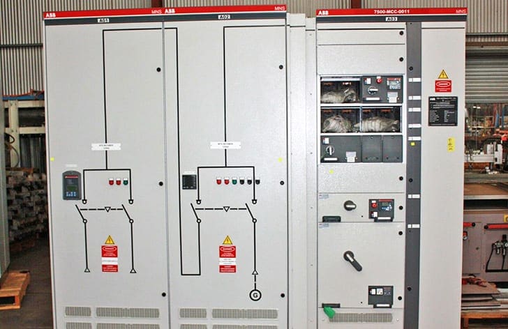
Main LV switchboard (+1NE) for power supply of waste water treatment plant (WWTP) can be supplied from each one of two transformers (-T1 and -T2), or from diesel genset (-DG). Parallel operation of transformers is not foreseen.
In general, WWTPs are not considered to be critical consumers. However, if necessary precautions during hydraulic design aren’t taken, potential overflows and severe material damage may occur during power supply outage. In this case, ATS is realized as a part of the main LV switchboard, so no additional separate cubicle is used for that purpose.
Control logic is done by PLC, which is used to handle exclusively automatic transfer function. Three line diagram of the power supply is given in Figure 2.

This is a real case example, which successfully operates for more than two years. Note that every switchgear device for connection with a power source (-Q1, -Q2, -Q3) is equipped with motorized gear for spring charging. It is a necessary condition for automatic open-close sequence realization. Otherwise, springs would need to be charged manually before each and every closing.
Related electrical guides & articles


Miodrag Kokotovic
Graduated from Faculty of Electrical Engineering, within University of Belgrade, in the field of electrical power systems. Expert in electrical part of tender preparation, design, procurement, construction and commissioning of treatment plants and pumping stations, electrical power quality and energy management.Profile: Miodrag Kokotovic
