
Estimated Study Time: 13 minutes
ATS operational requirements
In a previous article I explained the role of the automatic transfer system and the operational requirements – three modes of operation: manual mode, automatic mode, and auto mode failure.
 Automatic transfer system explained in detail - Operational requirements (photo credit: Jobimet.pl)
Now let’s cover the following topics and try to explain the concept of transferring power in details:
- Initiation of Transfer
- Dead-Bus Considerations
- Generator Starting
- Completion of Transfer
- Re-Transfer to Normal Source
- Open-Transition Re-Transfer
- Closed-Transition Re-Transfer and
- Unusual Conditions
1. Initiation of Transfer
In the automatic mode, the transfer system must be able to react to source failure by initiating the transfer. For this purpose, it is necessary for the mode logic to know the condition of the normal and alternate power sources. This is typically accomplished via undervoltage (device 27) and negative-sequence voltage (device 47) relays, as shown in Figure 1.
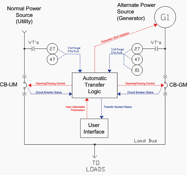
Frequency relaying is usually not required for utility sources as the frequency isquite stable, and not affected by changing load conditions within the facility.
Also, at the beginning of the startup cycle of a generator, the frequency is zero and will ramp up to the nominal frequency (typically 60Hz) as part of the startup process. For these reasons, under- (and possibly over-) frequency relays (device 81) are used for generator sources in addition to the under- and negative-sequence voltage relays.
Because overvoltage can be an issue when operating on generator power (for example, if the voltage regulator fails or the generator is called upon to absorb an excessive amount of reactive power), overvoltage (device 59) relays are occasionally used as well (not shown in Figure 1).
The pickup and time delay levels for these relays are functions of the system itself and the amount of time that abnormal conditions can be tolerated. For example, the undervoltage relays are typically set to pick up when the voltage level falls to 80% of nominal. The negative sequence voltage relays are typically pre-set to respond to the loss of a single-phase but may be adjustable.
Frequency relays must be set very carefully to avoid nuisance operations on normal load swings. It should be noted that these relays are typically for use by the automatic transfer system only, and are separate from the relays or generator control package functions which provide protection for the generator. Careful coordination is required to insure that the automatic transfer relays will always react before generator protective relays.
The indication from these relays to the automatic transfer logic is typically in the form of a single binary input, i.e., “source normal” or “source abnormal”. Upon receipt of a “source abnormal” signal when operating on utility power, the automatic transfer logic must respond.
Typically, this response is delayed to insure that the abnormality is not a transient condition, in order to prevent an unnecessary transfer. When the system is supplied via utility power this will allow the utility system to attempt clear the fault through reclosing.
Once the source failure time delay has expired, the automatic transfer system opens the circuit breaker for the affected source, starting the automatic transfer process.
Go back to ATS Operational Requirements ↑
2. Dead-Bus Considerations
Once a transfer operation has been initiated and the system has been disconnected from its normal source of supply, a suitable time delay must be given to allow the residual voltage from spinning motors to decay before the system is transferred to the alternate source.
For the example system of Figure 1, this will almost always be inherently be accounted for due to the generator start-up time, however, the logic should incorporate controls to insure this.
In general, any time a system bus is de-energized due to automatic transfer action a dead-bus delay should be coded into the transfer logic. Typical dead-bus delays are 2 – 5s.
Go back to ATS Operational Requirements ↑
3. Generator Starting
For the example system of Figure 1, a signal is provided to initiate generator starting. In general, this will be a requirement any time one of the sources of power is a generator or generators unless the generator(s) is used for cogeneration aswell as standby power.
Typically, this signal is a contact closure; once the contact is closed the generator(s) will start up and will run until the contact is opened, at which time the generator will begin a cool-down cycle.
Other variations exist, however in general the management of the generator cool-down cycle should remain under the control of the generator(s) control system rather than the automatic transfer system.
Go back to ATS Operational Requirements ↑
4. Completion of Transfer
After the alternate source is available and the required dead-bus delay has expired, the transfer system must close the alternate-source circuit breaker to supply the system from the alternate source. In the example system of Figure 1, the alternate-source circuit breaker is CB-GM.
For a main-tie-main system as shown in Figure 2, the secondary bus tie circuit breaker would be the circuit breaker that is closed.
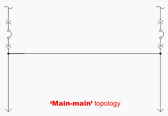
For the main-main topology arrangement, one of the bus tie circuit breakers would normally remain closed all of the time, and the second tie circuit breaker would be the circuit breaker that is closed to complete the transfer.
Go back to ATS Operational Requirements ↑
5. Re-Transfer to Normal Source
The normal source, when it returns, typically starts a timer in the automatic transfer system. This timer is present so that re-transfer will not occur until the normal source has been shown to be stable. The time delay is known as a return of source time delay and is typically set from 5 – 15 minutes.
Go back to ATS Operational Requirements ↑
6. Open-Transition Re-Transfer
As its name implies, open-transition re-transfer entails de-energizing the system prior to reenergizing it with the normal source. This requires a dead-bus delay as discussed above. In the example system of Figure 1, the circuit breaker CB-GM would open, a dead-bus delay would transpire, and circuit breaker CB-UM would close to complete the re-transfer.
The disadvantage to this method of re-transfer is that it requires the system to take a second outage in order to be restored to the normal source. However, it does not require additional equipment to accomplish.
Go back to ATS Operational Requirements ↑
7. Closed-Transition Re-Transfer
Closed-transition re-transfer requires the paralleling of the normal and alternate power sources for a brief time period prior to separation from the alternate power source. Where a generator(s) is involved, this requires synchronizing the generator(s) with the normal power source.
This synchronization may be accomplished passively, by simply waiting for the generator(s) to fall into synchronism with the normal source, or actively, by driving the generator(s)into synchronism with the normal source.
In general, passive synchronization is less expensive and can be accomplished with a simple synchronism checking relay (device 25), however the generator is not guaranteed to fall into synchronism with the utility source and the resulting energy transfer during the transition can damage the generator and other system components.
Active synchronization avoids these problems but is more expensive since a generator synchronizer and additional control signals between the automatic transfer system and generator control system are required.
The time period during which the sources are paralleled is usually very brief, no more than 2 -3 cycles, in order to keep the heightened exposure of the system which occurs to as brief a time as possible. This heightened exposure results from the elevated fault-current levels that exist with the sources in parallel, and also due to the exposure of the system to supply a fault on the normal source via the alternate source. If both the normal and alternate sources are separate utility services the utility may have restrictions on the ability to perform closed-transition re-transfer.
The advantage of closed-transition re-transfer is that the system does not have to experience another outage during re-transfer.For the example system of Figure 1, circuit breaker CB-UM would close once synchronization is achieved (passive or active), then circuit breaker CB-GM would open to complete the re-transfer.
Go back to ATS Operational Requirements ↑
8. Unusual Conditions
Unusual conditions can occur during the automatic transfer process. For example, the normal power source could fail, only to be restored during the dead-bus time delay before the alternate source is connected to the system. How the automatically transfer system responds during such conditions has traditionally been a function of the skill of the transfer system designer and the requirements of the facility.
The basic philosophy for automatic transfers in mission-critical environments is to transfer the system if the condition of the normal source is in doubt, so long as the alternate power source is known to be available and it is safe to do so, and most automatic transfer systems for these environments are designed with this goal in mind.
Go back to ATS Operational Requirements ↑
Reference // Critical-Power Automatic Transfer Systems – Design and Application by Bill Brown, P.E., Jay Guditis, Square D Critical Power Competency Center
Related electrical guides & articles


Edvard Csanyi
Hi, I'm an electrical engineer, programmer and founder of EEP - Electrical Engineering Portal. I worked twelve years at Schneider Electric in the position of technical support for low- and medium-voltage projects and the design of busbar trunking systems.I'm highly specialized in the design of LV/MV switchgear and low-voltage, high-power busbar trunking (<6300A) in substations, commercial buildings and industry facilities. I'm also a professional in AutoCAD programming.
Profile: Edvard Csanyi

Very nice coverage of the ATS concept with the basic functionality. Is there webinars available?