
Estimated Study Time: 10 minutes
Automatic Transfer System (ATS)
Although the basic operational requirements of any automatic transfer system are as given in this technical article, the equipment which is used to implement the automatic transfer system can vary.
 Equipment Used To Implement Automatic Transfer System - ATS (on photo: Robotic Parking Systems Generator Transfer Switch; credit: parkithere.wordpress.com)
The following is a list of commonly encountered variations regarding the automatic transfer system equipment //
- Switchboard or Switchgear?
- Logic Platform (PLC)
- Circuit Breaker Control and Interlocking
- User Interface
1. Switchboard or Switchgear?
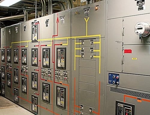
The power equipment used to facilitate the transfer, for low voltage systems, is commonly either a UL 891 switchboard or ANSI C37.20.1 low voltage power switchgear. Which is used is dependent upon the system design and where in the over-all power system the equipment is located, however the following general guidelines apply:
When automatic transfer is closer to service
For automatic transfer “higher” in the system (closer to the service), ANSI low voltage switchgear is generally preferred due to is compartmentalization and the use of drawout low voltage power circuit breakers, which have short-time withstand capabilities.
When automatic transfer is farther from service
For automatic transfer “lower” in the system (farther from the service), a UL 891 switchboard may suffice. However, drawout circuit breakers should be considered even if a UL 891 switchboard is used.
Lack of short-time withstand on molded-case circuit breakers is a big factor here.
2. Logic Platform (PLC)
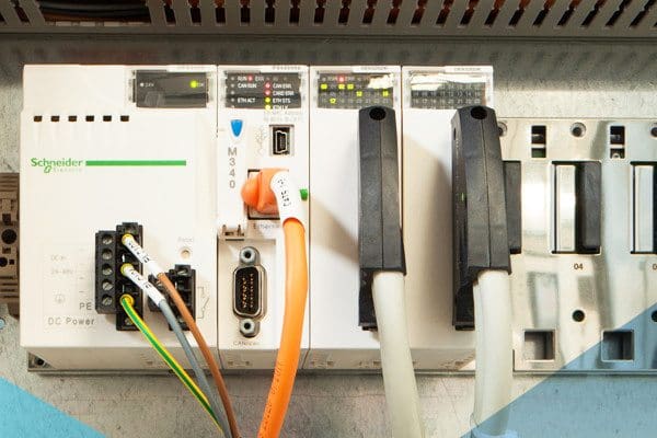
The automatic transfer logic may be supplied by either discrete control relays or a programmable logic controller (PLC), as shown in Figure 1.
In times past, this was generally a choice of flexibility (the PLC) vs. robustness (discrete relays). In recent years, however, PLC’s have undergone significant improvements in reliability and robustness, to the point that they are now the preferred method for implementing automatic transfer scheme logic.
Discrete control relays, on the other hand, must be re-wired to make changes to the automatic transfer logic, and more complex logic generally requires more control relays and wiring.
Another advantage of a PLC is its ability to communicate digitally with external devices. This makes more sophisticated user interfaces possible, as will be discussed below. It also allows remote access to the transfer system if required.
3. Circuit Breaker Control and Interlocking
Interlocking is the restriction of operation of devices, usually for safety reasons. For an automatic transfer system, the most common interlocking required is interlocking to prevent out-of synchronism paralleling of power sources (or prevention of paralleling at all in many cases).
When the automatic transfer system logic is provided by a PLC, this interlocking may be implemented in a hard-wired fashion, that is, outside of the PLC or as part of the PLC program.
In general, use of hard-wired interlocking is preferred, to allow an extra measure of safety should the PLC fail. Similarly, manual control for automatically operated circuit breakers may be implemented in a hard-wired fashion or via the PLC. It is generally recommended that at least the circuit breaker tripping function be implemented outside the PLC.
Manual control for automatically-operated circuit breakers is generally implemented via an external control switches, with the manual close control (and often trip control) on the circuit breaker access-restricted via a cover to force use of these control switches.
4. User Interface
This is the most customizable part of the automatic transfer system equipment. In general, two options are available:
- Discrete controls or
- Touch screen
Discrete Controls (switches, indication lights)
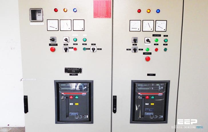
Discrete controls take the form of control switches and pilot lights mounted on the equipment. An example of this is given in Figure 2:
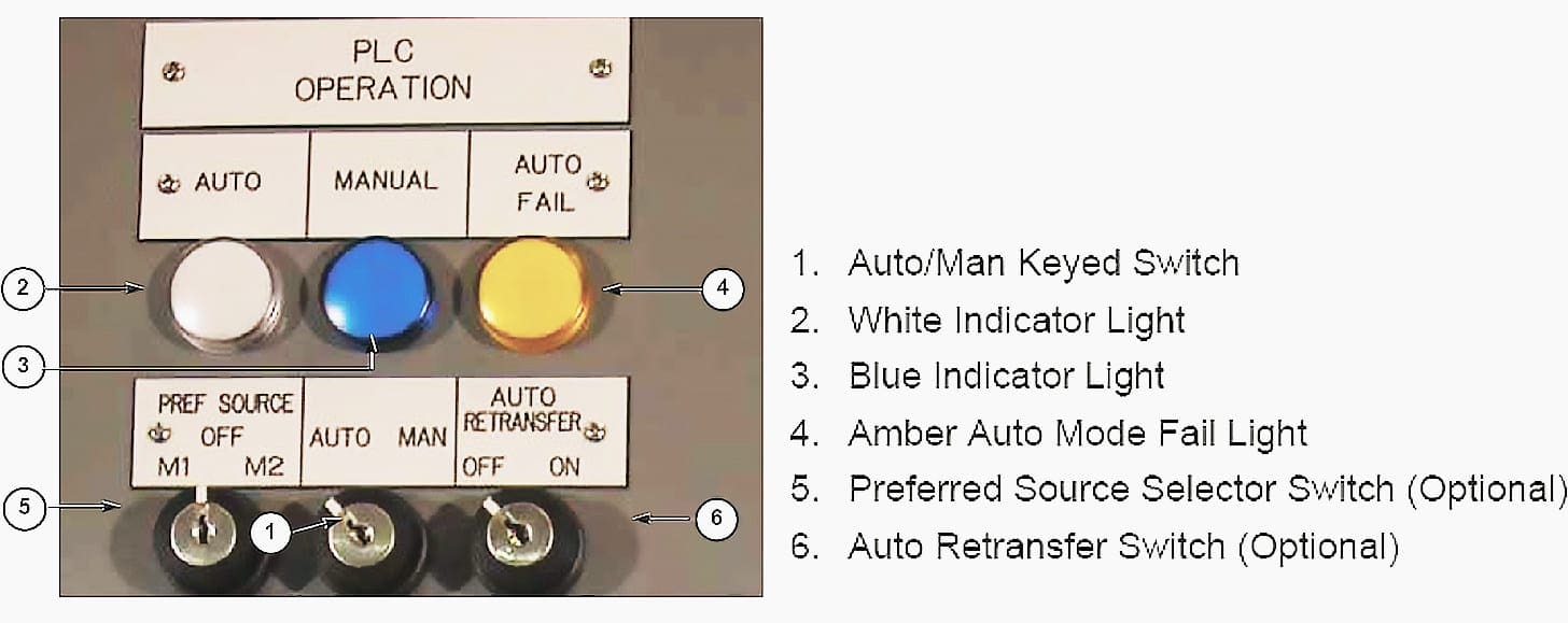
In Figure 2, “AUTO”, “MANUAL”, and “AUTO FAIL” pilot lights indicate the three modes of operation described in earlier published article.
A keyed auto/manual mode selector gives control of the operating mode, a keyed automatic retransfer on/off switch provides a means to enable or disable automatic retransfer, and a keyed preferred source selector allows either power source to be considered as the normal source.
In addition to the controls shown in Figure 2, the following are also commonly available:
- Open/Closed Transition re-transfer selector
- Source Available Indicators
- PLC low-battery indicator
- Transfer in Process indicator
- Source Failure Test Switches
Like discrete relay control logic, discrete controls must be planned to the last detail early in the specification process and provide limited flexibility for change.
Touch screen
When a PLC is used for the automatic transfer logic, a touch screen is an option for the user interface. A touch screen can provide a wealth of detail regarding the automatic transfer system status, and adjustability in several areas which aren’t typically available with discrete controls.
An example of a touch screen interface is shown in Figure 3:
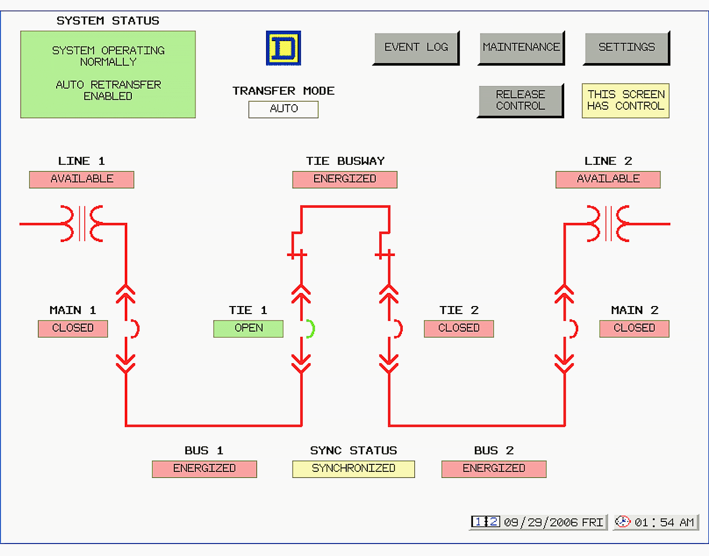
The touch screen interface in Figure 3 includes:
- An active mimic single line diagram which changes color to denote energization of system components
- Source available indicators
- Breaker status indicators,
- A transfer system status summary
- The ability to change numerical settings such source failure, dead bus, and source restore timers
- Quick manual transfer of the system from one source to the other in manual mode
- An event log which captures automatic transfer events for diagnostic purposes.
Touch screen control interfaces for automatic transfer systems do usually include at least one discrete switch and indicators, namely the auto/manual mode selector and its associated indicators.
4.3 Multiple User Interfaces
The use of multiple user interfaces is possible. Such an arrangement may be desirable due to the need for remote control of the system. In planning such an arrangement, careful consideration should be given to the number of interfaces and which interface overrides if control is attempted by more than one interface at a time.
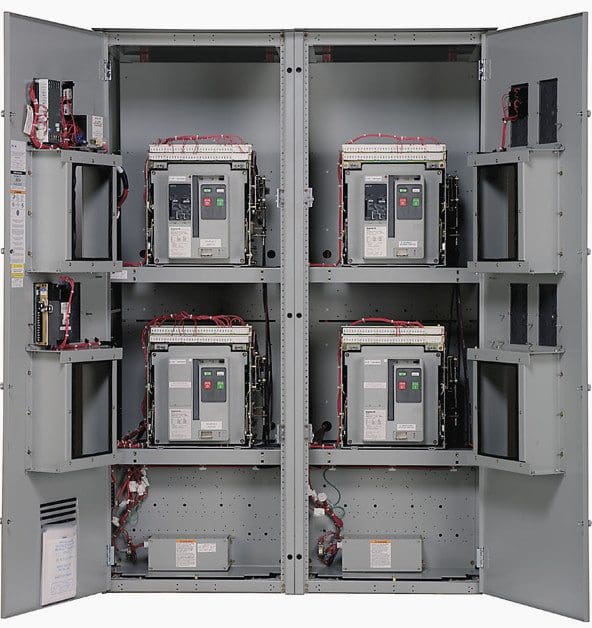
ATS panel (automatic transfer switch)
Reference // Critical-Power Automatic Transfer Systems – Design and Application Bill Brown, P.E., Jay Guditis, Square D Critical Power Competency Center
Related electrical guides & articles


Edvard Csanyi
Hi, I'm an electrical engineer, programmer and founder of EEP - Electrical Engineering Portal. I worked twelve years at Schneider Electric in the position of technical support for low- and medium-voltage projects and the design of busbar trunking systems.I'm highly specialized in the design of LV/MV switchgear and low-voltage, high-power busbar trunking (<6300A) in substations, commercial buildings and industry facilities. I'm also a professional in AutoCAD programming.
Profile: Edvard Csanyi

My premium registration is not going through. I am in Ghana.
I really like this page, i am an electrician of formation(2years), with my Higher National Diploma in Electrical Power Systems, at least it is helping me to master and acquiring more knowledge even though my present situation is not permitting me to realise my dreams,but hope to be one day,close to EDVARD Csanyi to learn more.thanks