
Estimated Study Time: 21 minutes
Automation in distribution systems
Nowadays, it seems that everything we do tends to be somehow automated. The very same is happening in electrical distribution systems. The distribution system at the medium voltage (MV) or low voltage (LV) levels is designed using different structures such as radial, double radial, open ring, and closed ring. Each one is selected based on load priority and the desired reliability level.
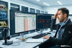
 The essentials of automation applied to distribution systems via PLCs, SCADA, IEDs, and RTUs (photo credit: svitovyr.com)
Accordingly, the system switching in case of emergency operating conditions is either manual or automatic, depending on the permitted duration of interruption periods and obviously the nature of loads.
The distribution systems feeding the industrial and commercial loads must be automated in most cases. Distribution system automation helps to raise the reliability level by decreasing the interruption duration, isolating the faulty parts, keeping the system equipment functioning, and automating the required switching processes during system operation.
This technical article explains the basics of automation applied to electrical distribution systems using PLCs, SCADA, IEDs, and RTUs.
- Distribution System Automation (Example of a Commercial Office Building)
- SCADA System
- SCADA Components
1. Distribution system automation
To what extent is it possible to decide the capability of automation applied to the distribution systems?
It depends on the size of the network, the nature and amount of load, and the type of system equipment. When the distribution system grows and becomes more complicated, is the automation sufficient to achieve optimal performance and to operate satisfactorily and securely? This is the question to be answered by the following discussion.
It is required to install standby generators as a backup to the utility supply to avoid the uncertainty in utility power reliability and damage in the event of power failure. In this situation, an interlock between the generators’ switches (circuit breakers) and the utility feeder CB is needed to avoid paralleling between them.
In addition, it is necessary to install transfer switches on each floor to allow the standby-generated power to flow into each apartment directly without passing through the utility meters (Figure 1).
Figure 1 – Schematic drawing of main lines of feeding a commercial building
As a result of these requirements, a lot of equipment needs to be distributed throughout the building:
- An interlocking panel for each generator located in the control room near the main switchboard (utility switches),
- Transfer-switches panel located at the DP of each floor, and
- The interconnection between the equipment and the control room.
It is clear that the space required for the control room will be large, and the number of wires needed between panels and remote points is also increased.
The operator monitors the system operation and the equipment functionality via the control room to know the position of each switch (open/closed/emergency), to visually diagnose the system status during a utility outage, and to diagnose the fault. These monitoring functions, traditionally, need a very large number of indicating lamps and warning alarms.
Imagine the difficulties and confusion that the operator is subjected to because of the large number of interconnecting wires and indicators. Also, do not forget the difficulties and time consumed in commissioning and testing the system. On the other hand, the load is increasing continuously and its nature may change resulting in a probable redesign of the distribution system by adding new equipment or making changes in the wiring system that may be difficult to implement.
Data processing results in information about the system status, energy management system (EMS), economic dispatch, interconnection pricing of energy, and any other useful application the workstation is programmed to perform. The information about the system status can be sent to the PLC to execute the corresponding control commands while the other information is used for system planning, maintenance, and operation.
With the workstation, the operator is able to display graphically on the screen the single-line diagram of the distribution system and any other visual display needed by utilizing user-friendly interaction through windows.
This system with high data acquisition and reporting requirements (but with limited control) is defined as SCADA.
The SCADA system can be easily adapted to any change in the application field as it can be integrated with other systems, for example, the protection system. Consider a power system involving the protection relay as shown in Figure 2.
Figure 2 – Protection mechanism
In this diagram, the current and potential transformers send samples of phase currents and phase voltages to be used as inputs to the protection relay. In turn, if these inputs violate prespecified values, the relay sends a tripping signal to the CB to be opened. To guarantee a correct performance for this protection mechanism, it must be ensured that the protection relay is working properly.
It needs to do another test to verify that the data generated by the protective functions are correctly communicated to the SCADA system. In this case, knowledge of the exact numerical representation of the data transmitted by the communication circuit is an important factor.
Figure 3 – Testing of the relay by using a simulator

Where,
- V = voltage;
- I = current;
- f = frequency.
Disadvantages of the relay systems and the advantages of the SCADA systems can be summarized as below:
Disadvantages of the Relay Systems
- Complicated control systems;
- Expensive systems;
- Systems need more space;
- Control relays consume more power, generating more heat;
- Relays are used only for on/off control;
- Any change in the control program needs rewiring of the relays; and
- It is difficult to troubleshoot and diagnose the fault for complicated control systems.
Advantages of the SCADA Systems
- Self-diagnostics and easily maintained;
- The capability of arithmetic functions implementation;
- Easy to program and reprogram;
- The facility of communication with other controllers or a master host computer;
- The ability of PLCs to move past simple control to more complex schemes as proportional/integral/derivative (PID) control;
- Industrial plant SCADA can be viewed as a distributed control system (DCS); and
- The capability of the graphical user interface (GUI) and visual display of system status.
More details about SCADA, definitions, components, communication, and others are given in the forthcoming paragraphs.
2. A SCADA System
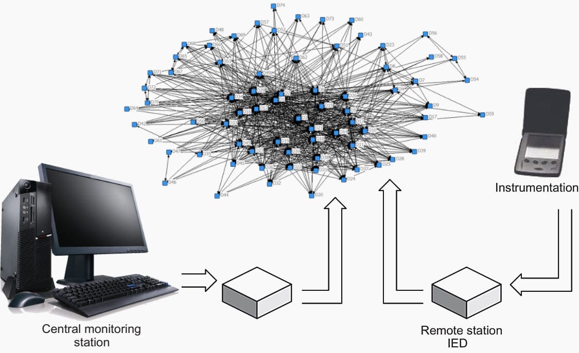
SCADA system stands for supervisory control and data acquisition system. It refers to the combination of telemetry and data acquisition. It commences with measurement of the data by specific devices in the field of application and collected via intelligent electronic devices (IEDs), then transferring these data to a master station to implement the necessary processing and control algorithms.
The results of processing are displayed on a number of operator monitoring screens, while the control actions are conveyed back to the field of application in real-time. See Figure 4 below.
Figure 4 – Elements of a SCADA system
2.1 Telemetry
Telemetry is the initial step in applying SCADA by defining the technique used for measuring the data (voltage, current, speed, etc.) from different locations in the real-time process and transferring it to the IEDs such as remote terminal units (RTUs) or PLCs in another location through a communication circuit.
2.2 Data Acquisition
Data acquisition refers to the method used for accessing and collecting the data from the devices being controlled and monitored, and to be forwarded to a telemetry system ready for transfer to the various sites. The data may be analog or digital gathered by sensors such as ammeters, voltmeters, speedometer, and flowmeter.
It can also be data to control equipment such as actuators, relays, valves, and electric motors.
Further Reading – Implementation of modern interlocking and data acquisition in HV system
Implementation of modern interlocking and data acquisition in HV system
3. SCADA Components
The SCADA system consists of four components as follows.
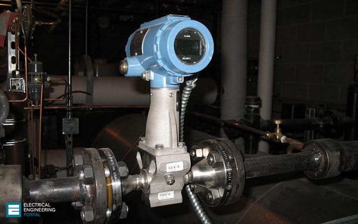
3.1 Instrumentation (Sensors)
This component refers to the devices used for monitoring certain parameters such as sensors and the devices used for controlling certain modules such as actuators. In general, these devices are connected to the equipment or machines being monitored or controlled by the SCADA system.
Their main function is to convert the parameters from the physical form to electrical form as continuous (analog) or discrete (digital) signals readable by the remote station equipment (RTUs or PLCs).
Figure 5 – Installed Steam Flow Meter
3.2 Remote Stations (RTU/PLC)
The measuring devices (first component) connected to the plant being monitored and controlled are interfaced to the remote station. Functions of remote stations are
- Gathering data from the different devices in the plant being monitored and controlled;
- Holding the data gathered in its memory and waiting for a request from the master station (master terminal unit [MTU]) to transmit the data; and
- Receiving data and control signals from MTU and transmitting the control signals to the plant devices.
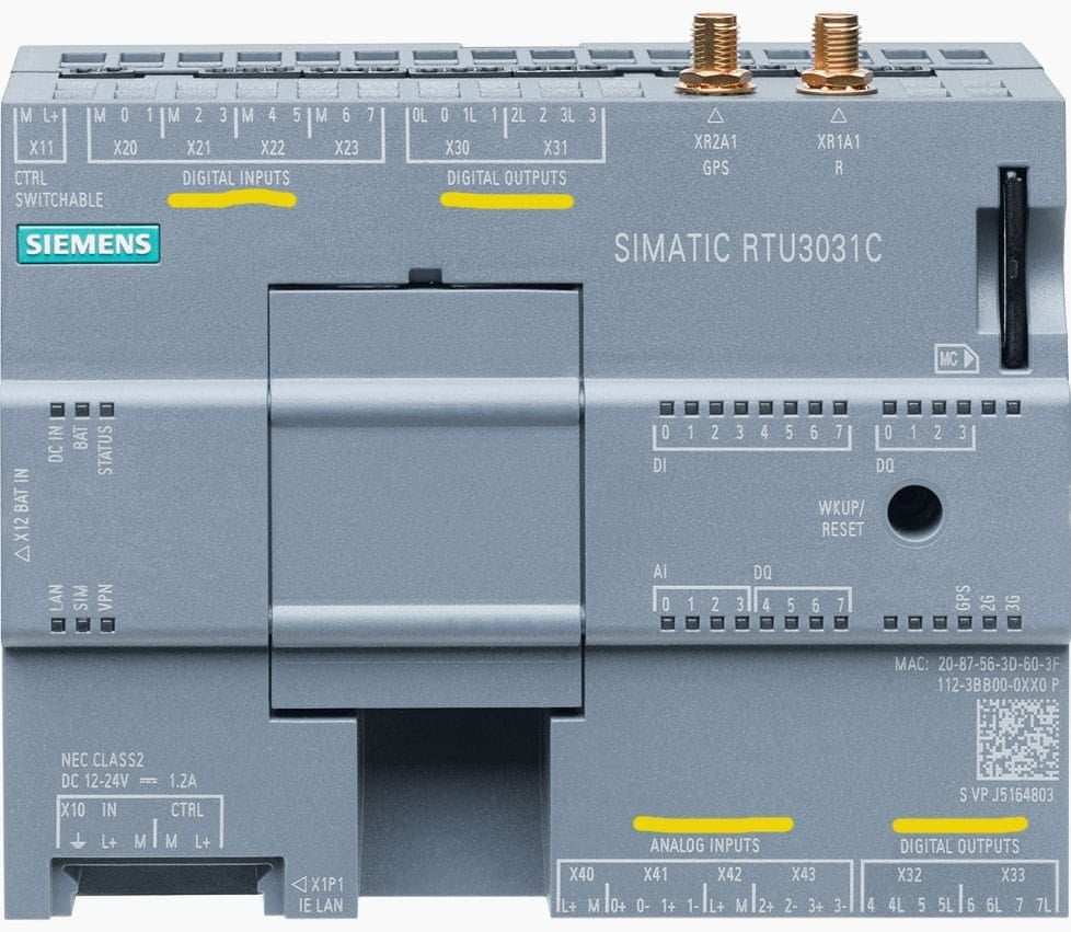
The remote station is either RTU or PLC. The RTU is used effectively in the event of difficult communications. Its inputs and outputs are shown in Figure 6.
Figure 6 – Remote terminal unit: inputs/outputs

The RTU has digital/analog inputs and outputs with light-emitting diode (LED) indication (selectable per channel), optically isolated for surge protection, and also protected against short circuits. On the other hand, the PLC is usually expected to be already available in the plant processes, so it is of great worth to be used also in the SCADA systems.
It’s worth saying that both the RTU and PLC have been greatly improved in the last ten years.
Figure 7 – Details of remote terminal unit: inputs/outputs (Siemens Simatic RTU3030C)
3.3 Communication Networks
The geographically dispersed RTUs are connected to the MTU through a variety of communication channels, including radio links, leased lines, and fiber optics. The design of both RTUs and MTU is largely affected by the availability limitation and high cost of communication channels.
The configuration of the communication system depends on:
- Number and location of RTUs;
- Number of points at RTUs and required update rates; and
- Available communication equipment, techniques, and facilities.
The SCADA communication techniques include modulation, multiplexing, message format, and information transfer.
3.3.1 Modulation
To convey information from one point (sending end [SE]) to another point (receiving end [RE]) through a communication channel, it must be modulated at the SE and demodulated at RE. This means that it is necessary to transmit a signal with a change from SE to RE where it is detected. This change can be carried out by either a change in signal amplitude or change of signal frequency or change of signal phase.
The demodulator at RE detects the change in the signal and outputs the transmitted information.
If the information transmission is only in one direction, it is called “simplex channel”, and if it is in the two directions but not simultaneously, it is called “half duplex”. Finally, if the transmission is in the two directions and simultaneous, it is called “full duplex”.
3.3.2 Multiplexing
In the SCADA system structure, it is needed to transmit information from different locations to one point, that is, multi-transmitter to one receiver. Economically, the best method is to use a single communication channel for many pieces of information.
This is known as “multiplexing” and can be carried out by one of two basic techniques: (1) frequency division multiplexing (FDM) and (2) time-division multiplexing (TDM).
Figure 8 – Frequency division multiplexing
In the FDM technique, each piece of information is transmitted over a dedicated part of the available communication channel spectrum (Figure 8). For the TDM technique, each piece of information is transmitted as part of a serial digital message over a separate span of time and demultiplexed by the receiver into the individual pieces of information (Figure 9).
Figure 9 – Time-division multiplexing
3.3.3 Message Formats
The transmission of information in both directions between the MTU and RTUs using TDM techniques requires the use of serial digital messages. All messages are divided into three basic parts:
Message Establishment – Which provides the signals to synchronize the receiver and transmitter and the unique RTU address;
Information – Which provides the data in a coded form to allow the receiver to decode the information and properly utilize it; and
Message Termination – This provides the message security checks and a means of denoting the end of the message. Message security checks consist of logical operations on the data, which result in a predefined number of check bits transmitted with the message. At the receiver, the same operations are performed on the data and compared with the received check bits.
The message is accepted if they are identical, otherwise, a retransmission of the original message is required.
3.3.4 Information Transfer
As it is clear in the preceding sections, the information in SCADA systems is transmitted from the RTUs to the MTU and also from the MTU to the RTUs. Therefore, it is not sufficient to just transmit the information correctly, but it must also be done securely.
The techniques of checking the information errors must be applied.
Figure 10 – MTU Inputs/Outputs
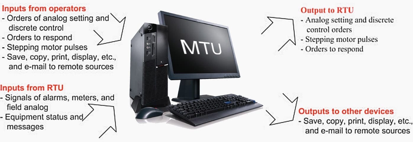
3.4 Master Terminal Unit (MTU)
It is also called “central control station, or central station, or SCADA master”. It is considered as the heart of the system where its main functions are:
- Making the communication, gathering data, storing information, sending information to other systems;
- Processing the data gathered by remote stations to generate the necessary actions; and
- Interfacing with the operators mainly via monitors and printers. The inputs and outputs of the MTU are shown in the above Figure 10.
Source: Electric distribution systems by Abdelhay Sallam
Related electrical guides & articles


Edvard Csanyi
Hi, I'm an electrical engineer, programmer and founder of EEP - Electrical Engineering Portal. I worked twelve years at Schneider Electric in the position of technical support for low- and medium-voltage projects and the design of busbar trunking systems.I'm highly specialized in the design of LV/MV switchgear and low-voltage, high-power busbar trunking (<6300A) in substations, commercial buildings and industry facilities. I'm also a professional in AutoCAD programming.
Profile: Edvard Csanyi

DCS-Distributed Control System (not SCADA) can be the main Control System- integrating all PLC, RTU’s ,FI, stand alone microcontrollers ,Fire and Gas/Safety System, Solar, in a power plant for High rise buildings using various subsystem communication protocol too. Advantages besides level 2 /level 1 based on ISA/Purdue model- can be easily integrated to level 3 and level 4 systems providing overall efficiency and cyber security and even cloud/remote operation and monitoring. DCS is much bigger in capacity and flexibility.
The content is vey useful and informative. Thank you for share this with us. I gained very good knowledge about scada system. Keep share.
Communication channels I. e different data cables form part of the system and their details and limitations also to be covered.
Hi there
What a very important, educational and interesting information. During my Internship I got training in SCADA, PLC, Telemetry and etc, now I am looking for a company that I can join to further my experience in Automation. I am looking for a volunteery work so that I gain more knowledge in the interesting field of automation and I think your company would the perfect place.
I want learn too more about sccada sistem
Hello Andy, are you talking about this technical article “The essentials of automation applied to distribution systems via PLCs, SCADA, IEDs, and RTUs”? This technical article is free of charge, you can read it, don’t you?
It would be better if free content would be available. Really the contents are very informative and useful.
This technical article is free of charge.