
Estimated Study Time: 10 minutes
Autotransformer Connection
An ordinary transformer consists of two windings called primary winding and secondary winding. These two windings are magnetically coupled and electrically isolated. But the transformer in which a part of windings is common to both primary and secondary is called ‘Autotransformer’.
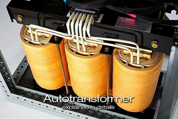
In Autotransformer two windings are not only magnetically coupled but also electrically coupled. The input to the transformer is constant but the output can be varied by varying the tapings.
The autotransformer is both the most simple and the most fascinating of the connections involving two windings. It is used quite extensively in bulk power transmission systems because of its ability to multiply the effective KVA capacity of a transformer.
Autotransformers are also used on radial distribution feeder circuits as voltage regulators.
The connection is shown in Figure 1 below.

The primary and secondary windings of a two winding transformer have induced emf in them due to a common mutual flux and hence are in phase. The currents drawn by these two windings are out of phase by 180◦. This prompted the use of a part of the primary as secondary. This is equivalent to common the secondary turns into primary turns.
The common section need to have a cross sectional area of the conductor to carry (I2−I1) ampere. Total number of turns between A and C are T1. At point B a connection is taken. Section AB has T2 turns. As the volts per turn, which is proportional to the flux in the machine, is the same for the whole winding, V1 : V2 = T1 : T2
When the secondary winding delivers a load current of I2 Ampere the demagnetizing ampere turns is I2T2. This will be countered by a current I1 flowing from the source through the T1 turns such that,
I1T1 = I2T2
A current of I1 ampere flows through the winding between B and C. The current in the winding between A and B is ( I2 − I1 ) ampere. The cross section of the wire to be selected for AB is proportional to this current assuming a constant current density for the whole winding. Thus some amount of material saving can be achieved compared to a two winding transformer. The magnetic circuit is assumed to be identical and hence there is no saving in the same.
To quantify the saving the total quantity of copper used in an autotransformer is expressed as a fraction of that used in a two winding transformer as:
Copper in autotransformer / copper in two winding transformer
= ( ( T1 − T2 ) I1 + T2 ( I2 − I1 ) ) / T1I1 + T2I2
Copper in autotransformer / copper in two winding transformer
= 1 – ( 2T2I1 / ( T1I1 + T2I2 ) )
But T1I1 = T2I2 so,
The Ratio = 1 – ( 2T2I1 / 2T1I1 ) = 1 – ( T2/T1 )
As the space for the second winding need not be there, the window space can be less for an autotransformer, giving some saving in the lamination weight also. The larger the ratio of the voltages, smaller is the savings. As T2 approaches T1 the savings become significant. Thus autotransformers become ideal choice for close ratio transformations.

The autotransformer shown in Figure 2 above is connected as a boosting autotransformer because the series winding boosts the output voltage. Care must be exercised when discussing ‘‘primary’’ and ‘‘secondary’’ voltages in relationship to windings in an autotransformer.
In the case of a boosting autotransformer, however, the primary (or high) voltage is associated with the series winding, and the secondary (or low) voltage is associated with the common winding; but the voltage across the common winding is higher than across the series winding.
Limitation of the autotransformer
One of the limitations of the autotransformer connection is that not all types of three-phase connections are possible. For example, the ∆-Y and Y- ∆ connections are not possible using the autotransformer.
The Y-Y connection must share a common neutral between the high-voltage and low-voltage windings, so the neutrals of the circuits connected to these windings cannot be isolated.
A ∆ – ∆ autotransformer connection is theoretically possible; however, this will create a peculiar phase shift. The phase shift is a function of the ratio of the primary to secondary voltages and it can be calculated from the vector diagram.
This phase shift cannot be changed or eliminated and for this reason, autotransformers are very seldom connected as ∆ – ∆ transformers.
Advantages of the autotransformer
- There are considerable savings in size and weight.
- There are decreased losses for a given KVA capacity.
- Using an autotransformer connection provides an opportunity for achieving lower series impedances and better regulation. Its efficiency is more when compared with the conventional one.
- Its size is relatively very smaller.
- Voltage regulation of autotransformer is much better.
- Lower cost
- Low requirements of excitation current.
- Less copper is used in its design and construction.
- In conventional transformer the voltage step up or step down value is fixed while in autotransformer, we can vary the output voltage as per out requirements and can smoothly increase or decrease its value as per our requirement.
Disadvantages of the autotransformer
- The autotransformer connection is not available with certain three-phase connections.
- Higher (and possibly more damaging) short-circuit currents can result from a lower series impedance.
- Short circuits can impress voltages significantly higher than operating voltages across the windings of an autotransformer.
- For the same voltage surge at the line terminals, the impressed and induced voltages are greater for an autotransformer than for a two-winding transformer.
- Autotransformer consists of a single winding around an iron core, which creates a change in voltage from one end to the other. In other words, the self-inductance of the winding around the core changes the voltage potential, but there is no isolation of the high and low voltage ends of the winding. So any noise or other voltage anomaly coming in on one side is passed through to the other. For that reason, Autotransformers are typically only used where there is already some sort of filtering or conditioning ahead of it, as in electronic applications, or the downstream device is unaffected by those anomalies, such as an AC motor during starting.
Application
- Used in both Synchronous motors and induction motors.
- Used in electrical apparatus testing labs since the voltage can be smoothly and continuously varied.
- They find application as boosters in AC feeders to increase the voltage levels.
Used in HV Substation due to following reasons:
- If we use normal transformer the size of transformer will be very high which leads to heavy weight, more copper and high cost.
- The tertiary winding used in Autotransformer balances single phase unbalanced loads connected to secondary and it does not pass on these unbalanced currents to Primary side. Hence Harmonics and voltage unbalance are eliminated.
- Tertiary winding in the Autotransformer balances amp turns so that Autotransformer achieves magnetic separation like two winding transformers.
Related electrical guides & articles


Jignesh Parmar
Electrical Middle management professional having more than 22 years rich and dynamic experience in Project Execution / Project Management / Designing / Maintenance diversifies from Electrical Power Transmission (400KV/220KV/66KV)- Distribution(11KV/220V) to Lifts-HVAC-Ventilation-Fire Fighting-Fire Alarm-Lifts-CCTV-Stack Parking Works (High Rise Buildings, Townships, Shopping Complex, Commercial Complex, School, Temple).Profile: Jignesh Parmar

Which is economical, Constant Ohmic Impedance or Constant % Impedance Auto Transformer and why?
230KV/33KV 140MVA transformer shall be auto transformer or two winding power transformer? which will be better.
I have a 3phase@600v grounded service feed, I am feeding an auto transformer 6oov,3phase wye to a wye 3phase 480v. Do I need to bring any neutral or ground to the XOHO terminal? The field device does not require a neutral.
How do I figure the current on the high side of an auto transformer 138,000/69,000, for 100 MVA UNIT? I don’t believe that I can use the same high to low side ratio as in a regular distribution transformer, such as a 138 Kv/12.5 Kv. thanks………Raymond
Dear All,
Can anyone tell me the source where i can get modeling of three winding HV auto transformer( i.e. auto transformer with tertiary winding)
Regards.
Dear Mr. Jignesh / Mr Edward
with reference to Auto transformers, My case is exactly same as that of Mr. Sadulla Shaikh, asked on april 08, 2015, will you be kindly forward the replay.
With Best Regards
Anees
Original post :
SADULLA SHAIKH
APR 08, 2015
In Saudi Arabia the utility voltage is being gradually changed to the existing 220 V 3ph 60 Hz to 400 V 3ph 60 Hz by utility company SEC. I want to use a step-up transformer (about 500 KVA) 220/400 V 3 ph temporarily to do preparatory modification in the residential buildings in a complex (replacing/ modification of wiring, lighting,power and equipment etc) so that when SEC replaces its distribution transformer with 400 V the buildings are ready to accept the new system voltage. Two winding transformers are not locally available, if I use 3 ph Auto transformer star/star, common neutral grounded, is there any problem, please advise. I prefer dry type transformer to be located in the existing electrical room
Want to know about autotransformer starter for motor. Function , Selection parameters required for same to design for various motor ratings.
SIR, IHAVE A3PHASE AUTO TRANSFORMER, AVAILABLE SUPPLY IN MY LOCATION IS N,220-220-220.i MEANT 22OV THREE PHASE WITH NUTRAL,I WANT TO STEP DOWN IT TO NUTRAL, 127-127-127.THERE IS OPTION AVAILABLE , BUT WHEN I CONNECTED COMMON NUTRAN AND THREE 220V LINES TO 220V TAPPING, MSB TRIPPED, AGAIN i TRIED WITHOUT NUTRAL , REMAINS SAME.PROBLEMS,
PLEASE HELP ME TO CONNECT IT AS I WISHED..
THANKYOU
plz i need control wiring and power wiring diagram for 300hp ac motor starter.. urgently
Useless theoretical article… If you are using the advantage :” In conventional transformer the voltage step up or step down value is fixed while in autotransformer, we can vary the output voltage as per out requirements and can smoothly increase or decrease its value as per our requirement” then copper saving is meaningless… please clear your fundamentals before posting… this may help : http://sound.westhost.com/articles/variac.htm
Sir, What would be the phase voltages and line voltages of a 3 phase auto transformer on no load condition. Is there any difference in the voltages in any of the phases possible under no load condition . If any of the phases showing 0 voltage and other two phases showing equal voltages what would be the reason . please explain.
thanks& Regards
csnair
tel 8976199703
Sir, I hv a transformer having primary 230V & secondary 24V,5 Amp rating. I want to use autotransformer to use it as a voltage regulator to control current flowing thru a HOT Nichrome resistance wire 24swg & 12′ to 15′ lomg& having resistance of 1.08 ohm/ft.
Plz let me know the rating of Autotransformer & its connection circuit diagrame to enable to solve my issue.
Sir, I hv a transformer of 230V primary & 24V,5Amp as secondary rating. I want an auto transformer to be used as a voltage regulator as I want to control the current flowing thru the Nichrome Hot wire of 24swg 12″ to 18″ long & havibg a resistance of 1.08 ohms per ft.
Plz let me know the rating of Auto transformer to be used & its connection circuit diagram to regulate the current flowing thru Nichrome HOT wire.
In Saudi Arabia the utility voltage is being gradually changed to the existing 220 V 3ph 60 Hz to 400 V 3ph 60 Hz by utility company SEC. I want to use a step-up transformer (about 500 KVA) 220/400 V 3 ph temporarily to do preparatory modification in the residential buildings in a complex (replacing/ modification of wiring, lighting,power and equipment etc) so that when SEC replaces its distribution transformer with 400 V the buildings are ready to accept the new system voltage. Two winding transformers are not locally available, if I use 3 ph Auto transformer star/star, common neutral grounded, is there any problem, please advise. I prefer dry type transformer to be located in the existing electrical room.
sir why we are connecting booster always series with the feeder …….why should we not to the parallel……
is autotransformers used to boost a medium voltage distribution (20kV) utility line? if so, is it recommended in such appolication. The issue we have is that the local utility lines are always under voltage and thus cause lower than acceptable voltage drop in the low voltage distribution.
Thanks,
Explain the working principle of differential relay in power transformer for internal and external fault?
You’re posting to the wrong technical article. This is about auto-transformer. More information about differential relay try using search-box.
For example:
https://electrical-engineering-portal.com/transformer-differential-protection-principles
how to design a buck boost transformer in servo voltage stabilizer?
After greeting kindly if you have a self-winding transformer law clearly explained Aober.s. pleasure knowingly Ramadan White Egypt
HI. autotransformer difference power transformer??, figure and shema