
Estimated Study Time: 30 minutes
Auxiliary DC power system
The auxiliary DC control power system is considered the most crucial element of a protection, control, and monitoring system. The failure of the direct current (DC) control power can result in the inability of fault detection devices to identify faults, breakers to activate in response to faults, and the loss of functionality in local and remote indicator systems, among other consequences.
 Auxiliary DC power system used for fault detection, trip coils and remote operation
In a number of cases, the direct current (DC) system lacks redundancy, hence emphasizing the paramount need of reliability in the whole design. The auxiliary direct current (DC) control power system encompasses several components, including the battery, battery charger, distribution system, switching and protective devices, as well as any monitoring equipment.
The appropriate design, sizing, and maintenance of the many components of the direct current (DC) control power system are necessary.
This technical article is dedicated to the essential component of primary and secondary substations – auxiliary DC power system. This system comprises of a charger, batteries, DC distribution system, and monitoring system. It has a direct connection to the mechanism of fault detection, the operation of trip coils, remote operation, and other similar functions.
Many industrial operations, particularly electrical power distribution systems within plants, require extremely reliable auxiliary power supply. These requirements have grown in response to the rising usage of computer control systems and digital electrical network protective systems.
Control and protection circuits in some systems, such as motor control centers (MCC), can be powered by the same AC power that feeds the MCC bus. Individual control transformers are needed for each circuit in such instances. Most of the more complex control and protection systems, especially those that must function even when power to that section of the electrical network is disconnected, require more highly reliable power supply.
These power supply are typically based on DC-backed systems, with batteries providing the necessary energy storage.
- Battery-Based Power Supply Systems
- DC Distribution Systems
- Battery Types For Use in Substations and Switchyard Control Houses
- Battery Chargers
- BONUS: Download Auxiliary DC Control Power System Design Study (PDF)
1. Battery-Based Power Supply Systems
Battery-based power supply systems can be classified into two main categories: (1) systems that directly give DC power to the specific systems that require continuous energy, and (2) systems that ensure uninterrupted AC power by utilizing uninterruptible power systems (UPS).
The battery-based systems (1) necessitate the use of batteries, chargers, and a DC distribution system. In contrast (2), the UPS eliminates the need for a DC distribution system by employing an AC distribution system that is powered by an inverter system (or systems). This allows the UPS to generate the necessary AC power from the battery.
Moreover, high-speed static switches provide rapid transfer to an alternative source in the event of inverter or similar malfunctions, so ensuring the uninterrupted nature of the power supply. Supply systems that rely on direct DC distribution are powered directly by a battery system, hence eliminating the need for intricate switching backup or the complexity associated with an inverter.
In the industrial setting, it is common practice to supply AC power to control devices, such as programmable logic controllers (PLCs).
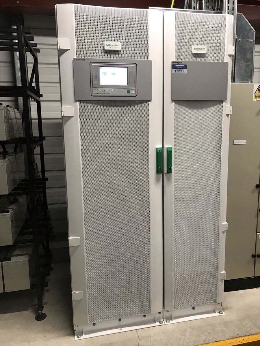
Figure 1 – Galaxy VM 160, 1125 kVA, 480 V 3-phase UPS power protection that seamlessly integrates into various industrial facilities
Nevertheless, a significant proportion of electronic systems function on direct current (DC) internally, and many of them offer or utilize DC power supply alternatives through the employment of AC/DC converters. Consequently, this equipment has the capability of feeding electricity from a direct current (DC) power distribution system as well.
In lieu of employing an uninterruptible power supply (UPS) for individual equipment necessitating AC input power, an alternative approach involves the utilization of individual or grouped inverters to supply these devices with power from a DC distribution system.
In instances of heightened severity, duplicated systems can be supplied power from two separate DC-battery-backed systems. Alternatively, specific equipment can be designed to be dual powered, ensuring that the failure of one power feed does not result in the shutdown of such equipment.
Dual-powered systems, however, need to be meticulously planned to prevent “common-cause” dangers from compromising both feeds. Several alternative battery types have been created to accommodate the wide range of duty cycles and standby times required by the batteries used in direct DC power supply systems.
In the case of uninterruptible power supply (UPS) batteries, they must be kept on a constant float charge when in standby mode, ready to give full power for the allotted amount of time should the AC power fail.
In spite of this, even when AC power is available, the peak power is pulled from the battery, as DC systems supplying switchgear and switchyards often carry large short-term demands, often exceeding the battery charger rating. As soon as the load is removed, the battery begins charging again instantly.
The battery charger often gives a float charge to the battery while also powering a steady-state load that counteracts the cyclic loading.
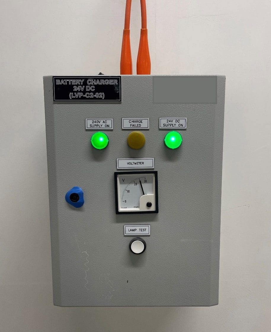
Figure 2 – LV panel battery charger
During the interruption of AC power to the charging system, the steady starting load and the peak demand must be fed. The switching activity in the substation provided by the battery determines the peak loads that occur in the event of a power outage. The switching sequence that is required to safely shut down and then to restore the AC power system are the most critical loads that need to be considered in developing such systems.
In addition to the pulsed cyclic loads, there may be additional loading circumstances that occur during a blackout, such as varying amounts of continuous load.
2. DC Distribution Systems
Battery, Battery Charger & Distribution Systems
The manner of connecting the battery, battery charger, and distribution systems is determined by the duty, the kind of load, and the necessity for redundancy in the system or in the chargers. Figure 3 depicts a common configuration for a 125 V system.
When feeding sensitive digital systems or when the distribution panel is located at a greater distance from the batteries and charger, as in this case, it is recommended to use the alternate connection provided for the battery-to-charger connection.
This approach has the benefit of reducing electrical noise on the DC bus and limiting interference into connected electronic and communication devices due to the battery capacitance behaving as a filter.
Short-term parallel operation can be tolerated without undue risk to both supplies if blocking diodes are incorporated into the crossover circuits. Similarly, a standby battery charger with an open circuit breaker is depicted in Figure 3. Again, by placing blocking diodes on each charger line and providing chargers designed to function in parallel, both chargers might be used simultaneously to split the load.
Figure 3 – 125 V DC supply system diagram
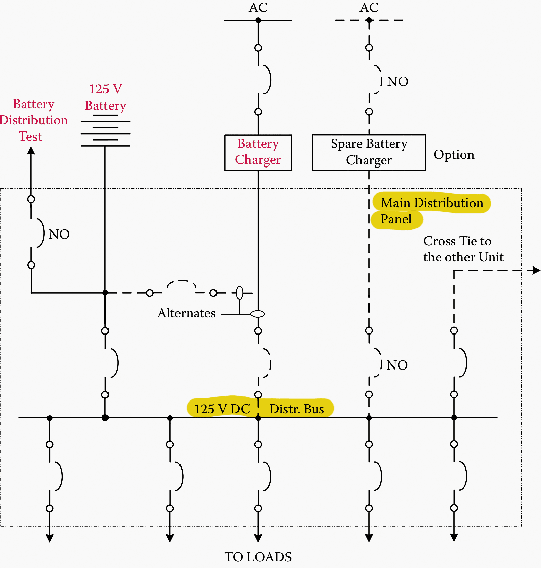
Notes:
- All breakers normally closed except those marked “NO”
- “– – – – – –” indicates optional or alternative features
- Fuse may be substituted for circuit breakers for any or all circuits except where transfer switching is required
It is crucial to reduce and, ideally, eliminate common-cause events that fail both systems in any dual, dual-supply, or redundant application instance. When determining whether to use live or dead transfer and/or dual powered devices, or whether to provide entirely independent redundant systems, this factor must always be taken into account.
Figure 4 depicts a modification to such a system that could be used with high-reliability DC supply.
In the case shown in Figure 4, the AC system feed and the DC transfer connections employ a crossover circuit rather than a single tie switch. This approach allows each switch or circuit breaker in the transfer arrangements to be isolated for maintenance without having to shut down both supply systems, providing a simple transfer connection for operation and interlocking.
Figure 4 – Increased-reliability dual DC auxiliary supply system
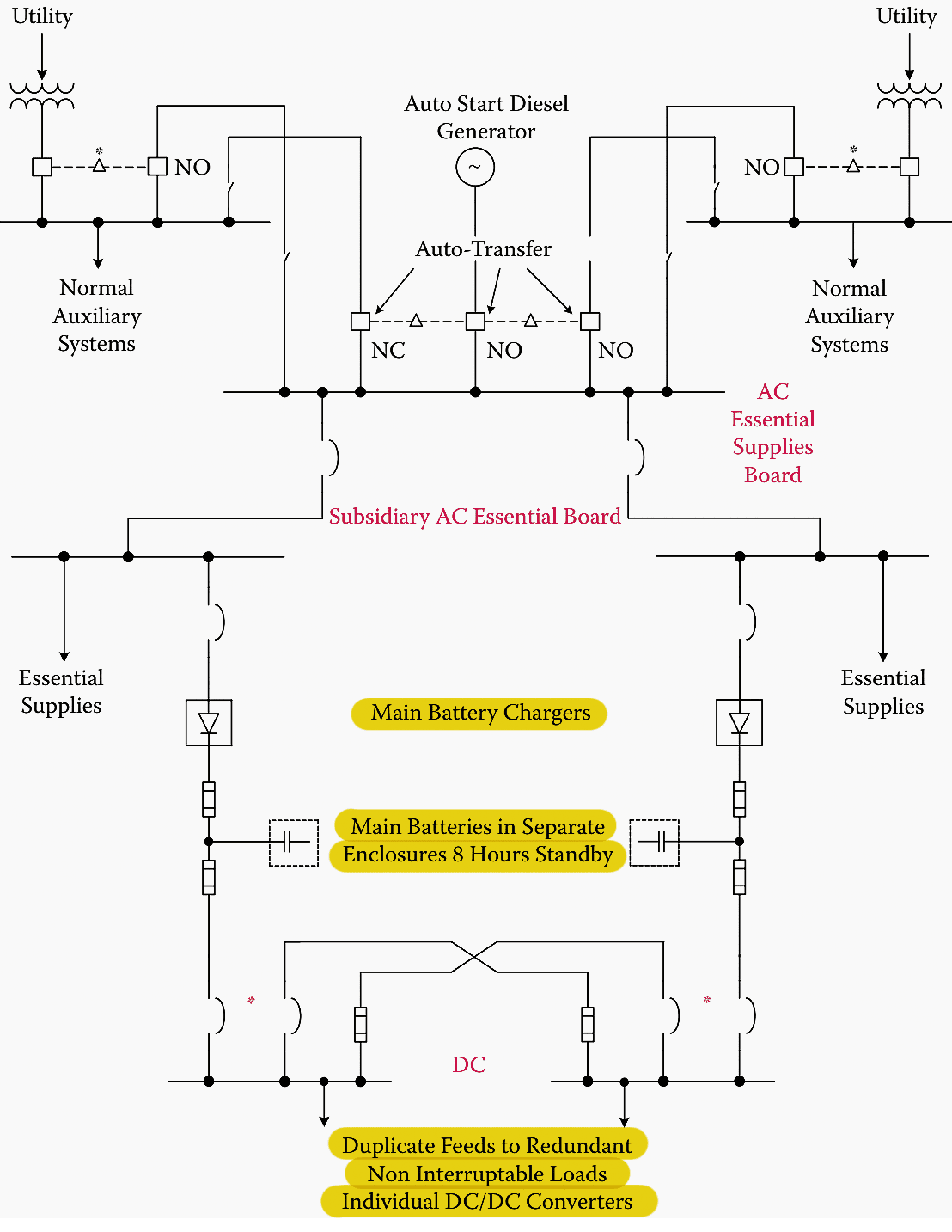
The diagram illustrates battery protection fuses. Further discussion of the utilization of these fuses to provide optimal protection for both the battery and battery cables is beyond the scope of this technical paper. Nevertheless, in this specific instance, fuses are installed on both the charger and feeder sides as a precautionary measure to prevent the possibility of a fuse operation that would disconnect the battery, while allowing the charger to continue supplying power to the DC loads independently.
The establishment of this connection is necessary in cases where the charger’s regulation and filtering mechanisms produce an output that is unsuitable for powering delicate electronic systems.
In the case of free-breathing and vented lead-acid batteries and other battery configurations that can lead to the accumulation of explosive by-products in battery rooms, the fuses must be located just outside the battery room in a properly shielded enclosure. To keep the most space between the battery terminals and the fuse box, it is best to run two separate cables from the fuse box to each battery terminal.
In order to mitigate the potential risk of a fault occurring between poles within the unprotected zone, it is imperative to undertake the necessary measures. Nevertheless, it is possible to utilize ordinary two-conductor cable for other components such as fuses, chargers, and distribution boards.
Figure 5 – Dual-battery system with single auxiliary supply distribution
Figure 5 presents a third illustrative scenario, depicting a dual supply and dual-battery configuration for both AC and DC power supply. AC and DC distribution supply are utilized in small hydroelectric producing stations. Nevertheless, the transfer switch configurations depicted between the chargers and the two batteries in this illustration, which enable each charger to charge either battery, are relatively uncommon.
The battery protection fuse in this configuration is a singular fuse located within the battery connection. This fuse is appropriate for situations where improved-performance chargers are utilized or if downstream devices possess a wide power supply voltage range and enhanced electrical noise tolerance.
The utilization of a single transfer switch configuration to alternate between two battery systems is commonly observed in substations where operators are present to carry out the transfer in the event of a breakdown in either battery system.
In instances when remote control of substations or automated transfer is deemed more suitable, the utilization of an interlocked autotransfer system may serve as a viable alternative to the single transfer switch. The feasibility of a continuous dual-feed configuration can be enhanced by incorporating blocking diodes and protective circuit breakers in each battery feed.
Additionally, a short parallel transfer (make before break) can be achieved by this modification.
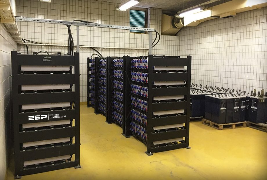
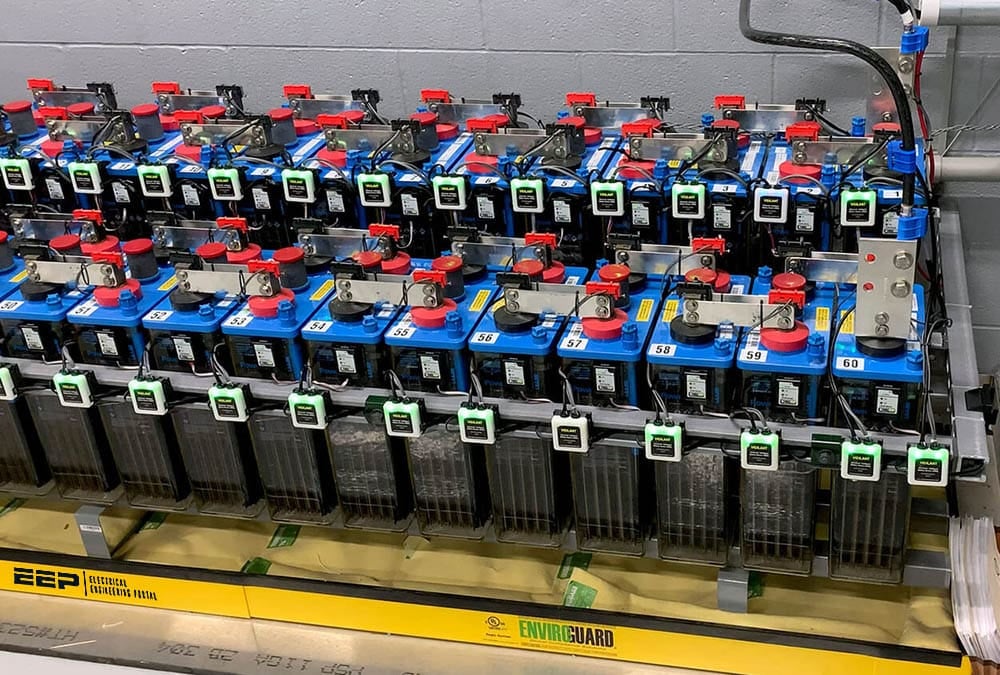
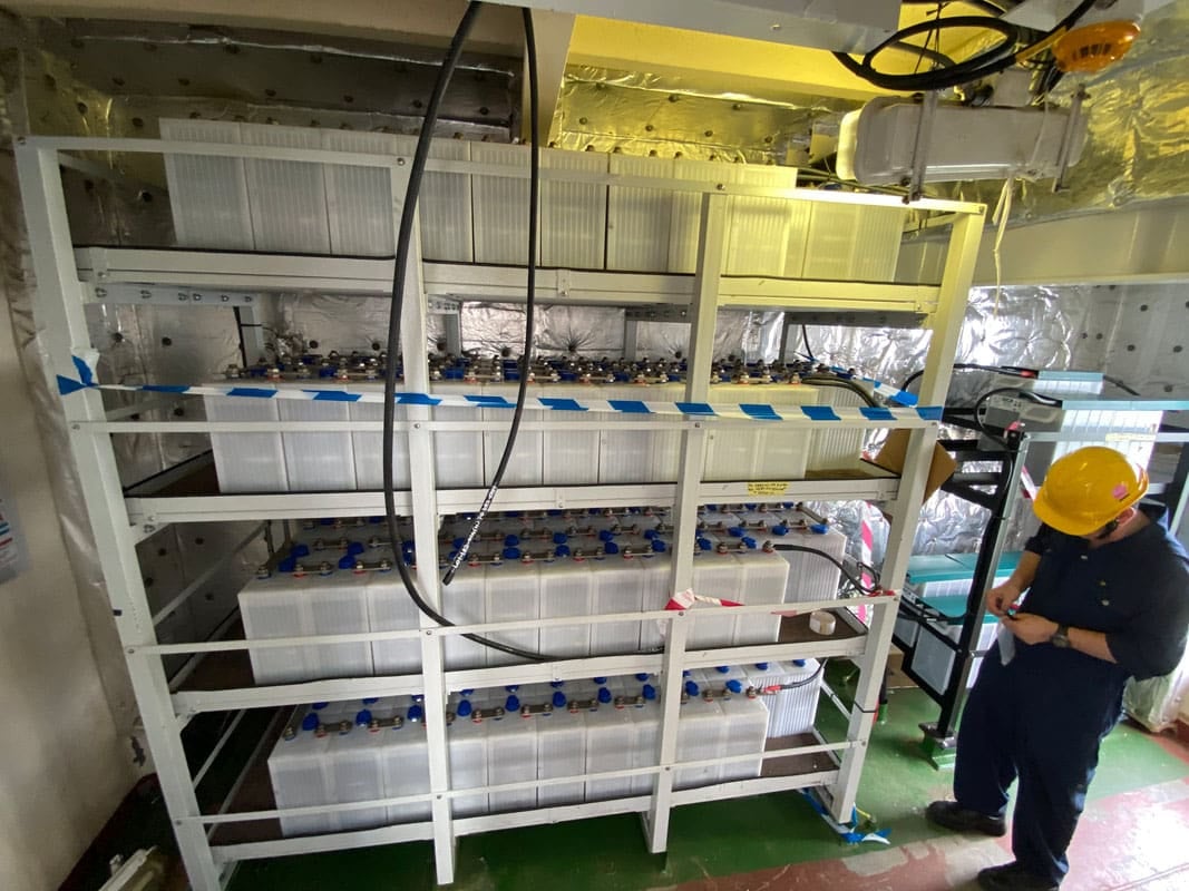
Figure 6 – Substation batteries
3. Battery Types
For Use in Substations and Switchyard Control House
In the past, the first varieties of big rechargeable batteries for use in industry and switchyards or power plants were all lead-acid batteries. At first, open-top batteries were utilized, as these batteries could be easily refilled, and their electrolyte levels and specific gravity could be checked with minimal effort. Because these batteries released substantial amounts of hydrogen, they had to be stored in rooms with their own ventilation systems.
Furthermore, in order to reduce the possibility of explosions occurring within these battery rooms, explosion-proof lighting equipment was installed.
These advancements also considerably decreased the boil off of electrolyte during the charging cycle. Charger settings were selected to limit the quantity of loss, and as a result, the necessity for frequent topping off of the electrolyte.
The vented-valve-regulated lead–acid (VRLA) cell is the product of more recent technological advancements. This type of lead–acid cell is hermetically sealed, with the exception of a valve that opens to the atmosphere when the internal gas pressure in the cell surpasses atmospheric pressure by a certain amount.
In order to reduce the amount of water that is used, VRLA cells offer a mechanism for the recombination of oxygen that is produced on-site as well as for the suppression of hydrogen gas evolution.
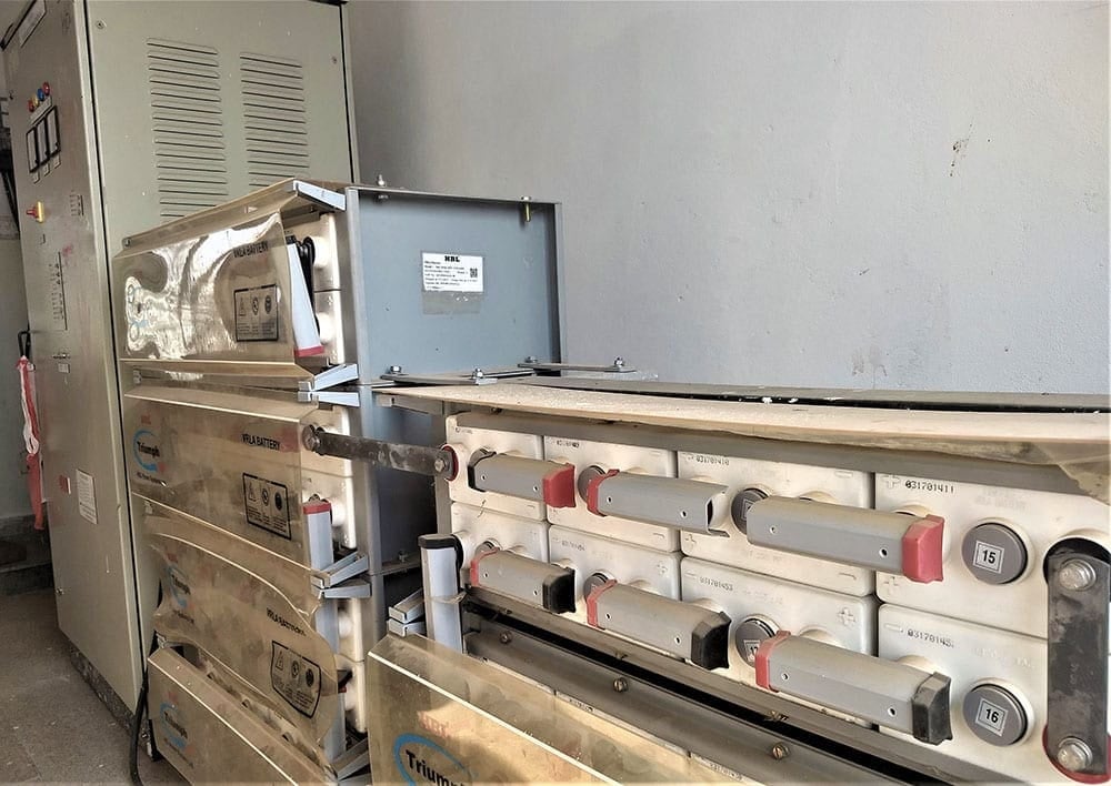
Figure 7 – VRLA Battery bank along with Float cum boost charger for a 33-11 kV substation
These are available in two distinct variations: the “absorptive glass-microfiber” (AGM) type, in which the electrolyte is housed within the microfiber “sponge,” and the “gelled electrolyte” “gel-cell” kind. Parallel discoveries in other types of batteries have resulted in the creation of a design for a big nickel–cadmium cell that is appropriate for use in large stationary rechargeable battery applications.
As a result of these improvements, the primary options available for the usage of such batteries in industrial settings and switchyards are:
- Lead–acid (antimony) VRLA
- Lead–calcium VRLA
- Nickel–cadmium
- Flooded-cell lead–acid (antimony or lead–calcium)
If this is not the case, the batteries will not function properly. However, their function is impaired both at high and low temperatures, and additional safety measures are required when operating outside of the temperature range of 0–40 degrees Celsius.
Nickel–cadmium batteries have a use in environments with temperatures ranging from -30 degrees Celsius to +50 degrees Celsius, despite the fact that they are more expensive, more difficult to dispose of, and therefore more expensive to recycle.
Because they are not acid-based, nickel-cadmium batteries do not release explosive gasses during the charge-recharge process. Because of this, they can be deployed more freely around a building, and they can even be mounted into cabinets, usually alongside their matching chargers.
As a result, they are commonly employed in places where DC power is required for only a few pieces of equipment, as both the equipment and the battery system can be installed in the same space.
Figure 8 – Nickel-Cadmium NiCd batteries
Use in local communication infrastructure is a typical example. However, it is important to highlight that nickel-cadmium batteries are subject to stricter environmental laws.
One notable benefit of lead-acid batteries is their ability to provide a more gradual voltage change during the discharge cycle compared to nickel-cadmium batteries. This characteristic enhances the sensitivity of charger control and alarms systems, thereby providing advanced warning signals prior to the occurrence of potentially hazardous levels of discharge.
The utilization of VRLA battery cells results in significantly reduced hydrogen generation, hence maintaining internal pressure within the specified limits of regulating valves and preventing hydrogen emission in the majority of instances. Therefore, their location necessitates fewer precautions.
Even if the risk of explosion and the requirement for ventilation has decreased, it is still necessary to comply with the numerous safety rules that call for very particular precautions to be taken in order to ensure the safety of personnel when it comes to preventing access to battery systems. Both of the many iterations of the VRLA battery have the electrolyte immobilized in the spongy substance or as a gel. Additionally, these batteries typically have their cells structured such that they are lying on their sides, which allows for more versatile placement options.
This makes it possible to combine the benefits of lead–acid batteries in terms of performance and cost with the advantages of nickel–cadmium batteries in terms of installation flexibility. Installation flexibility was previously one of the advantages offered by nickel–cadmium batteries.
Their operational simplicity and low maintenance requirements can contribute to the economic appeal of their use, despite the more frequent replacement of cells; their expected lifespan remains in the range of 10–15 years.
Recombination techniques are utilized in both varieties of VRLA cells; so long as the design duty and recharge cycles are adhered to, internal pressure rise issues and ventilation risks should be minimal.
Although the specific gravity and electrolyte level of flooded cells can be adjusted, they may still offer benefits in situations requiring more extreme duty cycles and rapid recharge, or where the duty cannot be readily regulated. Nevertheless, it will be necessary to stick to the safety measures recommended for the management of acid handling, venting, and explosive risk containment.
This includes the provision of shower facilities and eyewash stations, which were customary in older battery installations.
Further Study – Sizing of 110V DC charger for MV panels – Auxiliary power supply in power substations
Sizing of 110V DC charger for MV panels – Auxiliary power supply in power substations
4. Battery Chargers
In order to maintain the battery at full charge (float), the charger typically functions continuously to deliver a small current in addition to the continuous load. The battery is utilized to supply any surplus power and is recharged automatically once the intermittent load ceases. When there is a loss of AC power to the charger or when the charger malfunctions, the battery assumes the complete burden of the DC system.
The capacity of the charger must be sufficient to restore a totally discharged battery to full charge within a specified time period, while also providing power for the battery’s normal standing load. Using the following, the charger size can be calculated under such circumstances:
Charger capacity (amp) = L + (1.15 × C) / H
where
- L = continuous load, A
- C = battery capacity, A×h
- H = recharge time, usually between 8 and 10 h
It is common practice to assume that the continuous load is equal to the entire battery rating divided by the design standby time in situations where the full-duty cycle is unknown or subject to change. Because of this, the ampere rating of a charger is frequently greater than twice the comparable 8-h battery discharge rate, which is typical for station batteries.
If the battery and charger are going to be used in an area where temperature and altitude derating are in effect, the result of the preceding sizing study should be multiplied by 1/C1 for temperature and 1/C2 for altitude to account for these effects. At 55°C, a normal value for C1 would be 0.8, while at 1500 m, a typical value for C2 would be 0.9.
Particularly if valve regulated lead acid (VRLA) cells are used or if reduced gassing during recharge is desired, the charger must be tailored to suit the battery design and charging cycle needs of the particular battery type.
In order to comply with the audible noise weighting standards of the DC system, chargers utilized for communication equipment batteries must undergo filtration. Additionally, chargers that may be required to supply power even when the battery is disconnected must possess adequate filtering and voltage control mechanisms.
These measures are necessary to ensure that the DC supply and superimposed DC ripple remain within the tolerances specified for the load equipment.
Charging systems have the capability to operate with either single-phase or three-phase electricity, depending on the specific characteristics of the power source and voltage availability, as well as the electrical load requirements. Battery chargers, being commonly categorized as switched power devices, have the potential to generate harmonics that are fed back into the power supply. Therefore, it is imperative to exercise control over this phenomenon.
Large battery chargers are typically three phase and fed from the 600 V or 480 V power level in some applications because this is always easier to do with three-phase connectors and a higher voltage level available.
Suggested Reading – Learn how to operate an unknown energized low voltage switchgear (practical experience)
Learn how to operate an unknown energized low voltage switchgear (practical experience)
5. BONUS: Auxiliary DC Control Power System Design Study (PDF)
Download Auxiliary DC Control Power System Design for Substations in PDF format (for premium members only):
References:
- Industrial power systems by Shoaib Khan
Related electrical guides & articles


Edvard Csanyi
Hi, I'm an electrical engineer, programmer and founder of EEP - Electrical Engineering Portal. I worked twelve years at Schneider Electric in the position of technical support for low- and medium-voltage projects and the design of busbar trunking systems.I'm highly specialized in the design of LV/MV switchgear and low-voltage, high-power busbar trunking (<6300A) in substations, commercial buildings and industry facilities. I'm also a professional in AutoCAD programming.
Profile: Edvard Csanyi
