
Estimated Study Time: 20 minutes
The art of tripping and auxiliary
Tripping circuit breakers and operating alarms in control and protection applications usually require more than one relay contact. Tripping relays are used to multiply the number of contacts available, provide isolation between the source and system operating element and meet the required duty.
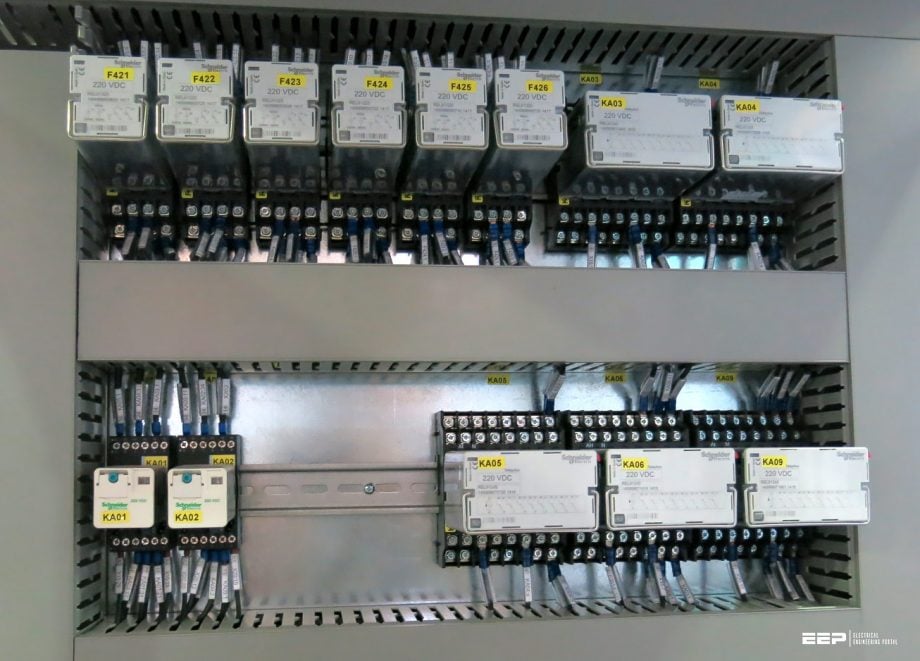 The essentials of necessary auxiliary relays in tripping and control applications (photo credit: Edvard Csanyi)
In some applications, the relay contacts may have to be rated to carry heavy and highly inductive currents and this requires large contacts and high contact pressures.
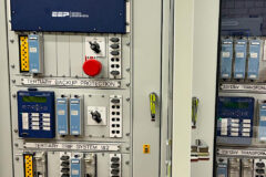
Auxiliary relays offer varying levels of functionality to best suit the tripping and control applications. They can be found installed in many control applications such as electrical utilities, power generation, electrical substations, transportation, industry, oil & gas, food & beverage, water treatments, mining, minerals, and metals.
1. Auxiliary relays in general
Examples of basic circuit breaker tripping schemes are given in Figure 1. The disadvantage of intermediate tripping relays is that they increase the overall fault clearance time by adding another stage in the fault clearance sequence. Therefore alternatives such as optoisolators, reed relays and solid-state switches may be considered to provide good isolation and faster responses.
Changeover ‘all-or-nothing’ relays may be divided into auxiliary and tripping classes. Tripping relays must have the following characteristics:
- Fast, with less than 10 millisecond operating times.
- High operating contact ratings to operate circuit breaker trip coils.
- Mechanically stable and shock-resistant.
- Must not be prone to maloperation.
- Have provision for a visual ‘flag’ or operation indicator in the relay case.
For throw-over or bistable relay contacts the convention is for illustration in the state which will apply when the initiating device is in the normally open state. For circuit breakers, the auxiliary switches are shown with the circuit breaker main contacts in the open position.
Figure 1 – Basic circuit breaker trip initiation schemes
Standard IEC 60255 ‘Measuring relays and protection equipment ’ gives the following nominal DC relay coil voltages: 6 V, 12 V, 24 V, 48 V, 60 V, 110 V, 125 V, 220 V, 250 V and 440 V. The IEC preferred working voltage for all-or-nothing relays is 110 to 80% of nominal. The systems designer should be careful when matching battery systems and relay coil voltages.
A 110 V nominal DC system when using Gaston Planté lead-acid cells will have a float charge of some 124 V DC. Therefore 125 V relay coils should be used and not 110 V coils. In addition, the substation battery voltage at the end of the discharge period could well be below the 80% minimum.
It is essential that the trip circuits do not maloperate owing to earth fault currents.
In the circuit shown in Figure 2, an earth fault on the wire between the protection relay contact and the trip relay could cause current to flow through the relay as the wiring capacitance on the negative side of the battery discharges. In a transmission voltage substation, there is a large amount of secondary wiring permanently connected to the substation auxiliary supply battery.
Figure 2 – Effect of earth faults on trip relay operation: (a) typical shunt reinforcing contactor system; (b) earth leakage path
Therefore a standard test for a tripping relay is that it should not operate when a 10 Farads capacitor charged to 150 V is connected across the relay coil. If the substation battery centre point is resistance earthed then there is also another path for the current to circulate.
It is usual to size this resistor to limit the maximum earth fault current to about 10 mA. As very light duty auxiliary relays will certainly operate at this current level they should not be used in protection trip schemes if spurious signals are to be avoided.
Table 1 – Performance of ABB’s trip relays
| Manufacturer: ABB | Heavy (button contacts) | Medium (finger contacts) | Light (reed relay) |
| Current carrying capacity (1 s) | 30–75A | 50 A | 2.4 A |
| Continuous rating | 6–10A | 5 A | 2 A |
| Making current L/R10 ms | 30 A | 30 A | 2 A |
| Breaking capacity: | |||
| • DC L/R<ms @ 24V | 10–20A | 4 A | 1 A |
| • DC L/R<ms @ 125V | 0.7–5A | 0.3 A | 0.16A |
| Operating times | 35–50ms | 20–40ms | 1–5ms |
| Operating burdens | 2.7–4W | 1.5W | 0.8W |
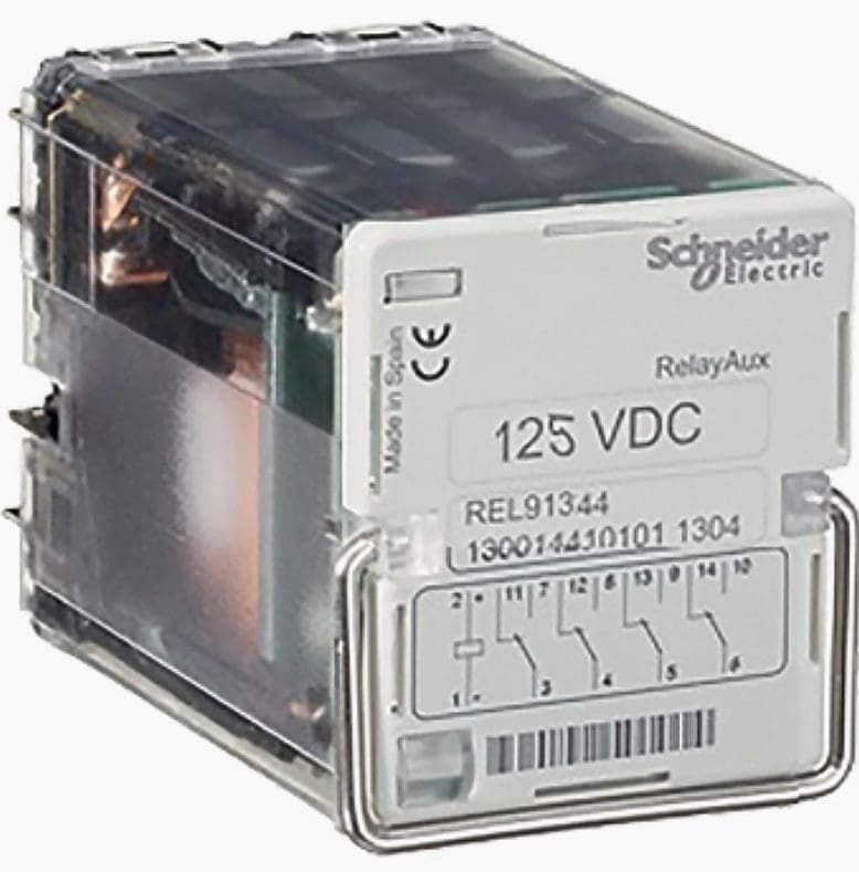
A typical trip relay is illustrated in Figure 3. The attracted armature relay is used for high-speed operation (20-40 ms) at high current levels. In order to avoid damage to the protection relay contact if it has to break the trip relay current or sustain it for a long length of time, a self-cut-off contact is incorporated which breaks the coil current when the operation is complete.
For self-reset relays, an ‘economy’ resistor is placed in series with the coil to limit the current once the relay has operated.
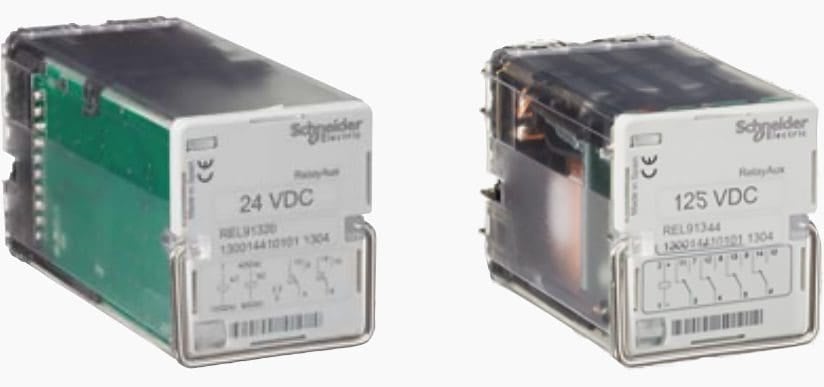
Figure 3 – Left: Trip circuit supervision relay; Right: Auxiliary supply circuit supervision relay, type RelayAux (Schneider Electric)
Go back to the Contents Table ↑
2. Types of auxiliary relays
Auxiliary relays may be divided into the following groups:
2.1 Instantaneous trip relays
Instantaneous trip relays, whose contacts change instantaneously from the rest position to the working position when the coil is energized. The contacts return to the rest position when the coil is no longer energized. This range includes relays with 2 and 4 contacts, with standard operating times (20 ms) or fast operating times (8 ms), depending on the manufacturer and the model.
Instantaneous trip relays can operate directly to the tripping and control circuit and usually have 4 changeover contacts.
Figure 4 – Instantaneous trip relay contacts
There are also instantaneous fast trip relays intended for tripping applications where high demanding requirements in operating time and breaking capacity are needed, such as the case of tripping HV and MV circuit breakers. They usually have 4 or 8 changeover contacts.
Figure 5 – Instantaneous fast trip relay contacts
Go back to the Contents Table ↑
2.2 Trip circuit supervision relays
Lockout trip relays are used for single-phase or three-phase circuit breakers. Through a small supervision current the whole circuit is supervised, in both positions of the circuit breaker (opened or closed). The correct state of the circuit is shown with a green LED on the front plate of the relay. The output contacts change their position if the relay detects a failure in the continuity of the circuit.
Figure 6 – Connection of trip circuit supervision relay for single-phase circuit breakers
Go back to the Contents Table ↑
2.3 Trip and lockout relays
Used to ensure that once a circuit breaker has been tripped by the protection scheme it cannot be reclosed either manually or automatically until the trip relay has been reset. The reset function may be either manual or electrical.
Trip relays with 2 stable positions for the output contacts. Depending on which coil is energized, the contacts will change from one position to the other. The design of trip and lockout relays have no consumption in permanence and prevent both coils from being energized simultaneously.
Nowadays, you can find Fast Trip and Lockout relays intended for tripping and locking applications where high-quality requirements in operating time and breaking capacity are needed. They usually have 4 or 8 changeover contacts.
Figure 7 – Fast Trip and Lockout relay contacts – Left: with 4 changeover contacts; Right: with 8 changeover contacts
If you want to learn more about lockout relays and their practical applications on mainstream switchgear and protection, visit the below article:
Suggested reading – Lockout relay in substation protection and control design
Lockout relay (master trip relay) in substation protection and control design
Go back to the Contents Table ↑
2.4 Auxiliary supply circuit supervision relays
Since small and reliable silicon diodes are available it is nowadays common practice to rectify the AC and use ordinary highly reliable DC relays. If AC relays are used the design must take into account the fact that the holding flux in the armature will fall to zero every half cycle. Small copper shading rings are sometimes employed to cause a phase shift sufficient to damp any flux reversal vibrations or relay chatter.
In order to avoid faulty alarms due to instantaneous supply voltage dips, the drop off time of the relay is delayed over 100 ms so those non-permanent failures of trip supply would not be considered.
Figure 8 – Auxiliary supply supervision relay, type RelayAux (Schneider Electric)
Go back to the Contents Table ↑
2.5 Time-lag relays (or timers)
Highly accurate solid-state timers are available by using digital electronics to divide down and count pulses from a known standard. The time delay may be derived from 50 Hz or 60 Hz mains, a simple free-running RC oscillator, an internal piezoelectric quartz crystal oscillator, reception of a calibrated radio beacon or satellite transmission.
Setting ranges of 0.02 to many hours may be obtained with an accuracy down to less than 0.3% of the set value. Clockwork, wound spring mechanisms and synchronous motors have also been used in the past with 10 to 1 timer ranges and 5 to 10% accuracy levels.
Simple diodes or RC networks may be applied to relays in order to slow down operation. The application of these delays helps prevent ‘races’ between circuits operating at slightly different speeds. A mechanical dashpot damper device is also used on some 400 V distribution air circuit breaker operating mechanisms.
Figure 9 – Time-lag relay contacts
Time-lag relays allow 16-time settings (from 30 ms to 99 h) and 10 different functions (all of it being easily adjustable from the front of the relay):
- Pick-up timing
- Pick-up timing acceleration
- Drop-out timing
- Flashing timing
- Special timing
This auxiliary relay with 4 contacts makes possible direct action on HV and MV switchgear.
Go back to the Contents Table ↑
2.6 Undervoltage relays
DC undervoltage relays are used to provide continuous trip circuit supervision or main substation DC distribution voltages. AC undervoltage relays are used to protect large motors from damage that could occur from running at low voltage, in mains failure monitors and in VT secondary circuits.
Again, solid-state relays offer advantages over older electromechanical types in terms of accuracy and have typical drop-off and pick-up voltage settings within 1% of each other without cost penalty.
Specifications should cover the following points:
- Single or adjustable setting
- Setting or setting range required
- Instantaneous or time-delayed operation
- Single or three-phase supervision
- Resetting ratio or adjustment range required
Go back to the Contents Table ↑
2.7 Underfrequency relays
Underfrequency relays are usually applied to the generation plants to avoid fatigue or excess vibration when running outside synchronous speed. The relays operate in conjunction with load shedding schemes in order quickly to bring the generation back into synchronism and up to speed.
Digital electronic underfrequency counter relays divide down and compare the supply frequency with an internally derived stable clock reference. A delay is incorporated in order to prevent anomalous operation under transient conditions (DC offsets under fault conditions, harmonics, voltage dips on large motor starting, etc.).
In contrast, telecontrol methods tend to operate out to primary substations rather than customer premises and therefore are less selective in the particular loads shed. The characteristics required are explained in the technical article “The art of load shedding and online applications in a power system under an emergency state“.
A useful formula for designing a load shedding scheme is:
![]()
where:
- H – total system inertia [MJ]
- L – system load [MW]
- G – system generator output [MW]
- ft – frequency at time t following load or generation change
- f0 – initial frequency
- t – time in seconds following disturbance
Figure 9 shows a typical set of time-frequency curves for various degrees of system overload with under-frequency relay trip setting points at 49 and 48 Hz. Several stages of load shedding are established in order to minimize outages whilst maintaining system stability.
Figure 10 – Underfrequency load shedding curves
The load shed should always slightly exceed the theoretical minimum required in order to avoid further, more drastic stages of shedding. A time delay between stages is necessary such that the effect of the first load shedding (which will take several hundred milliseconds depending upon circuit breaker operating times, generator inertia and generator governor response) can be determined before the second stage is started.
On a large steam generation system, up to five stages of load shedding may be applicable, whereas on a single gas turbine or light diesel installation only one or two stages with 300 ms delays might be applicable.
Suggested Course – Learn How to Depict Switchgear & Substation Single-Line Diagrams
Learn How to Depict Switchgear and Substation Single-Line Diagrams
Go back to the Contents Table ↑
Sources:
- T&D Electrical Engineering by Dr C. R. Bayliss
- RelayAux – Auxiliary relays for tripping and control applications by Schneider Electric
Related electrical guides & articles


Edvard Csanyi
Hi, I'm an electrical engineer, programmer and founder of EEP - Electrical Engineering Portal. I worked twelve years at Schneider Electric in the position of technical support for low- and medium-voltage projects and the design of busbar trunking systems.I'm highly specialized in the design of LV/MV switchgear and low-voltage, high-power busbar trunking (<6300A) in substations, commercial buildings and industry facilities. I'm also a professional in AutoCAD programming.
Profile: Edvard Csanyi

Thanks so much for the knowledge.
More graces and strength
guys
it seems my question might be unrelated to the subject but in the figures above is there an article which explains the numbers , for example
Fig 9 I can see the symbol of the Time-lag relay contacts
and there are numbers like
3 with 11
4 with 12
5 with 13
6 with 14
what are these numbers what do they explain?
very important introduction
I have one query, if my SF6 pressure on HD4 ABB CB goes to insufficient level, can i hold the circuit breaker from tripping, that can cause and impact tripping with huge production loss. And what can be the consequence of holding my CB on 280kpa insufficient gas sf6 pressure, please guide.
Well explained. Very informative.