
Short-circuit fault current limiter
Short-circuit fault current limiters come in a variety of kinds for use in low, medium, high, and extra high voltage systems. Some have been in service for many years, such as the traditional limited series reactor. Other technologies, such as solid state limiters and superconducting, have almost completed substantial research and development and are anticipated to be put to use in commercial applications soon.
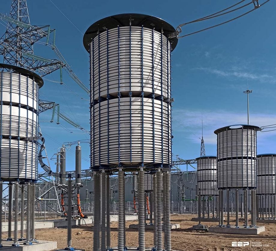 How to avoid unnecessary replacement of a switchgear by limiting short-circuit fault current (on photo: Dry-type current-limiting reactor with air natural cooling, intended to limit short-circuit currents in electrical grids of 35kV, 110kV, 220kV, 330kV and 500kV, and maintain voltage level, in case of fault; photo credit: SVEL)
Besides their main benefits of avoiding the otherwise unnecessary replacement of switchgear, fault current limiters introduce additional benefits caused by the reduction of stresses on equipment during short-circuit faults. A number of concomitant economic benefits include increased power plant life by limiting let-through current, lower thermal, mechanical and electrodynamical stresses of equipment, improved network capacity by allowing several transformers to operate in parallel and possibly lower need for spares.
As energy demand rises and more distributed generation and clean energy sources, like wind and solar, are added to an already overburdened system, the need for fault current limiters (FCLs) is being pushed by rising system fault current levels.
Additionally, when fault current levels rise, larger and frequently more expensive high impedance transformers are required. FCLs, in contrast to these transformers, operate normally with little to no impedance, resulting in a more stable system.
In this technical article, we briefly describe established and emerging fault current limiter technologies as well as their examples.
- Earthing resistor or reactor connected to transformer neutral
- Pyrotechnic-based fault current limiters
- Permanently inserted current limiting series reactor
- Series resonant current limiters using a bypass switch
- Limiters using magnetically coupled circuits
- Saturable reactor limiters
- Passive damped resonant limiter
- Solid state limiters using power electronic switches
- Superconducting fault current limiters
- The ideal fault current limiter
- Applications of fault current limiters
1. Earthing resistor or reactor connected to transformer neutral
An earthing resistor (NER) or reactor may be connected to the neutral of a transformer star connected winding in order to limit earth fault currents, i.e. single-phase and two-phase to earth. Usually, neutral earthing reactors are used on autotransformers such as those connecting 400–132 kV networks and 380 kV/365 kV to 110 kV networks.
Neutral earthing resistors are usually connected to the neutral of the lower voltage winding of distribution transformers such as on the 11 kV neutral of a star-connected winding of a 132 kV/11 kV transformer.
The ohmic value of the earthing reactor for use with existing transformers is usually a compromise between the desire to increase the reactance as much as possible to limit the short-circuit current and the need to limit the voltage at the transformer neutral point to within the insulation level of the winding.
Figure 1 – Neutral earthing resistor (NER)
Depending on application and network, there are several methods of neutral earthing including:
1.1 High or low resistance grounding
In commercial systems that must continue to function even after a fault occurs, like continuous process industries, high resistance grounding is used. In order to avoid triggering the circuit breakers, NERs often limit the current to a 10 Amps or fewer. When a fault occurs, protection mechanisms are engaged, enabling the system to swiftly identify and fix the issue or safely shut down.
At this point, there won’t be any damage.
Go back to the Contents Table ↑
1.2 Solidly earthed grounding
Solidly earthed grounding NERs are typically used in LV applications of 600V or less and connect the neutral point to earth. These systems reduce the problem of transient over-voltage but do not limit the fault current during a fault event.
Suggested Guide – Handbook for application of neutral earthing resistors (NERs)
Handbook for application of neutral earthing resistors (NERs) at the substation
Go back to the Contents Table ↑
2. Pyrotechnic-based fault current limiters
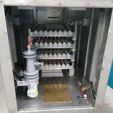
These fault current limiters, also known as ‘IS-limiter’, are widely used in low and medium voltage systems and industrial power systems at nominal voltages up to 40.5 kV with interrupting currents up to 210 kA symmetrical rms.
The IS-limiter is a device that consists of two parallel conductors as shown in Figure 2. The first is the main conductor that carries the load current under normal unfaulted system operating conditions. The second is a parallel fuse with a high breaking capacity that limits the short-circuit current at the first current’s rise and interrupts it at the next current zero.
Figure 2 – Insert and insert holder of the IS-limiter

Figure 3 shows the effect of IS-limiter operation where the two sources of fault currents are characterised by an rms current equal to 31.5 kA and a peak factor equal to 1.8 giving an initial peak asymmetric current of 80 kA.
The IS-limiter is activated by a small charge that opens the main conductor and diverts the short-circuit current to the fuse. The normal instantaneous current through the IS-limiter is monitored by an electronic measuring and tripping circuit. Both the current and its rate of rise are continuously evaluated and compared to selected set points.
If both set points are simultaneously reached, the IS-limiter trips and the total operating time to current interruption is 5–10 ms. After an operation, the IS-limiter insert (one unit per phase), i.e. the main conductor, the parallel fuse and the charge need to be replaced.
Since the current is generally limited and interrupted before the half cycle asymmetric peak is reached, as illustrated in Figure 3, the IS-limiter current will not contribute to this initial half cycle peak current.
Figure 3 – Performance of the IS-limiter
Go back to the Contents Table ↑
3. Permanently inserted current limiting series reactor
Short-circuit current limiting series reactors have been used in power systems at almost all voltage levels for decades. They introduce a leakage impedance into the current path which limits the fault current.
Because they are permanently inserted in the system, i.e. under normal unfaulted system conditions, they have several disadvantages. These include:
- they introduce a voltage drop,
- have active and reactive power losses,
- may adversely affect the optimum distribution of power flow in interconnected networks,
- may also adversely affect the transient and dynamic stability performance of power systems.
Suggested reading – Four ways to bolster the short-circuit withstand capability of HV transformers
4 ways to bolster the short-circuit withstand capability of HV transformers (in use)
Go back to the Contents Table ↑
4. Series resonant current limiters using a bypass switch
To eliminate the active and reactive power losses in bus tie applications using single reactor component, an alternative is to use a power frequency tuned resonant series inductor and capacitor combination. The combination has a zero impedance under normal operating conditions.
To limit the fault current, the capacitor element is shorted out using a fast closing bypass switch. A variant of this approach is to use a series/parallel arrangement of tuned inductors and capacitors in order to create two parallel tuned elements in series by the operation of a single bridging switch at the circuit mid-point.
Both circuits are shown in Figure 4.
Also, the shorting switch may have to close near zero voltage across the capacitor to avoid a very large transient current duty.
Figure 4 – Series resonant fault current limiters using a bypass switch in two designs
Go back to the Contents Table ↑
5. Limiters using magnetically coupled circuits
Figures 5 and 6 show two configurations of magnetically coupled circuits. Two windings, a primary and a secondary, having equal number of turns are shown. The two windings are connected so that the same current flows through them and the primary winding MMF balances that of the secondary winding.
During normal or unfaulted operation, the voltage induced across the self-inductance of the primary winding is cancelled by the voltage induced in the same primary winding due to the current flowing in the secondary winding, and vice versa. Therefore, the net voltage across each winding is zero.
A sensing and control circuit is required to detect the onset of short-circuit current and switch the device into the limiting mode.
5.1 Flux cancelling limiter with reverse secondary winding bypass
This is shown in Figure 5.
When an external short-circuit fault occurs, the coupling between the two windings is broken by immediately closing the normally open switch and opening the normally closed switch. This effectively open circuits the secondary winding and causes the primary winding to appear as a series reactor with an impedance ZR that acts to limit the short-circuit current.
Figure 5 – Fault current limiters using magnetically coupled circuits: flux cancelling limiter with reverse secondary winding bypass
The actions of the switches make the circuit appears as 1:1 transformer with an open-circuited secondary winding. The voltage rating of the normally closed switch is equal to the voltage across the primary winding under short-circuit conditions.
This switch only carries the normal load current. The current rating of the normally open switch is equal to the limited short-circuit current and under unfaulted system conditions, the voltage across this switch is zero because it is equal to the voltage across the secondary winding.
5.1 Flux cancelling limiter with reverse parallel to series reconnection
This is shown in Figure 6. When an external short-circuit fault occurs, the direction of the secondary winding is reversed so that the induced voltage adds to the voltage across the self-inductance of each winding, instead of subtracting, and hence doubles the effective impedance in series with the network.
The normally open switches carry the limited short-circuit current whereas the normally closed switches carry the load current.
Figure 6 – Fault current limiters using magnetically coupled circuits: flux cancelling limiter with secondary winding polarity changeover
Go back to the Contents Table ↑
6. Saturable reactor limiters
Saturable reactors have a non-linear voltage–current characteristic so that when the voltage across the reactor rises above a certain threshold, the reactor current increases disproportionately due to core saturation. As a result, its effective impedance reduces below that without saturation.
Figure 7 illustrates a saturable reactor with a DC and an AC windings that are wound orthogonally on an iron core.
The device operates in the saturation region under normal unfaulted system conditions and must be quickly taken out of saturation upon the onset of short-circuit current. The increase in impedance offered by this limiter is generally small and may not be sufficient if appreciable current limitation is required.
A conventional series iron core saturable reactor may also be used where saturation is obtained by injecting a DC current into the main winding.
Figure 7 – Orthogonally wound saturable reactor fault current limiter with DC control winding

Go back to the Contents Table ↑
7. Passive damped resonant limiter
Figure 8 illustrates one phase of a three-phase damped resonant limiter circuit using only passive components. The limiter consists of an isolation transformer whose primary winding is connected in series with the system and a capacitor is connected across its secondary winding. A non-linear resistor, e.g. a varistor, or a fast closing triggered switch, is connected in parallel with the capacitor and a damped tuned filter is connected in parallel with the varistor.
Under normal unfaulted system condition, the secondary circuit appears as a capacitor at 50 Hz that when transferred to the primary of the transformer, is equal to and hence cancels out the transformer’s leakage reactance. Therefore, at 50 Hz, the limiter appears as a short circuit except for the resistance of the transformer.
When a short circuit fault occurs in the power system, the increase in current flowing in the transformer’s primary winding causes a corresponding increase in the secondary winding’s current. The rise in voltage across the secondary winding impedance would cause the varistor or switch to conduct and short circuit the capacitor.
However, with series capacitors in transmission systems, sub-synchronous resonance phenomenon has occurred and caused damage to turbo-generator shafts.
Figure 8 – Passive damped resonant fault current limiter
Thus, the purpose of this circuitry is to provide damping at sub-synchronous frequencies. The circuit consists of a reactance XL1, and a ‘C’ filter whose XL2 and XC2 are tuned at power frequency (50 or 60 Hz), so that the damping resistor R is short-circuited at this frequency.
XL1, is used because the filter can not be connected across the main capacitor XC1 to avoid short-circuiting this capacitor. The value of XL1 is chosen so that at power frequency, the parallel combination of XL1 and XC1 appears as a capacitive reactance whose value is equal to the leakage reactance of the series transformer.
In summary, the limiter has a negligible impedance under normal unfaulted system operation and a fault limiting reactance equal to the transformer’s leakage reactance under short-circuit conditions. A damping circuit is included to reduce the risk of sub-synchronous resonance. The modelling of this limiter as a leakage impedance in short-circuit studies is straightforward.
Suggested course – Power Engineering Course: Generators, Transformers and Transmission Lines
Power Engineering Course: Generators, Transformers and Transmission Lines
Go back to the Contents Table ↑
8. Solid state limiters using power electronic switches
8.1 Series resonant limiter using thyristor protected series capacitor
Figure 9 illustrates this type of limiter which is based on a flexible AC transmission system series compensation device called the thyristor protected series capacitor. In parallel with the capacitor is a power electronic switch that consists of anti-parallel thyristors. Under normal unfaulted system operation, the thyristor switches are not conducting current, and the series inductance and capacitance are tuned at power frequency.
Therefore, only the inductor’s resistance remains in the circuit and this incurs active power losses. Under system fault conditions, the thyristor switches are made to conduct the fault current and bypass the capacitor thus inserting the reactor impedance into the fault path within a few milliseconds.
The reactor acts to limit the fault current.
Figure 9 – Fault current limiters using thyristor protected series capacitor
Go back to the Contents Table ↑
8.2 Series resonant limiter using thyristor controlled series capacitor
The circuit is illustrated in Figure 10 and is essentially a flexible AC transmission system series compensation device employing thyristor controlled series capacitor used for improving the power transfer capability of the network. Under normal system operating conditions, the thyristor conduction angles are small (firing angles are large), so that most of the current flows through the series capacitor.
The effective impedance of the parallel inductor/capacitor combination is capacitive. However, when a short-circuit fault occurs, the firing angle of the thyristors is quickly reduced, so that the parallel inductor/capacitor combination changes to inductive thus limiting the fault current.
Fault current limitation is generally an attractive by-product of these controlled series capacitor devices.
Figure 10 – Fault current limiters using thyristor controlled series capacitor
Go back to the Contents Table ↑
8.3 Solid state limiter using normally conducting power electronics switches
This type of fault limiter is illustrated in Figure 11. It consists of a power electronics switch that is connected in series in the AC system. A fault limiting resistor or reactor is connected in parallel with the switch.
Under normal unfaulted system operation, the switch conducts and carries the normal load current and the fault limiting resistor/reactor is short-circuited. When a system short-circuit fault occurs, the rising fault current is detected and the switch is turned off thus diverting the fault current to the parallel resistor/reactor which acts to limit the fault current.
A varistor may be connected in parallel with the switch to limit the transient voltage that appears across it. The switches may accomplish the current switch off using gate turn off thyristors or modern alternatives. Because they are normally conducting, the switches incur on-state active power losses and these are typically 0.1–0.2% of the throughput power.
Figure 11 – Solid state fault current limiter using normally conducting power electronics switches
Go back to the Contents Table ↑
9. Superconducting fault current limiters
A superconductor is a wire or a coil such as Bismuth-2233 or YBa2Cu3O7 that, when cooled, acts as a perfect conductor that has a zero resistance. Beyond a certain critical limit of a particular property, the conductor loses its superconductivity state and transition to a normal high resistive state. The property referred to is the conductor critical temperature, critical current or current density, or magnetic field.
Figure 12 illustrates the magnetic field and resistance/current, properties of a superconductor.
The transition from the superconducting to the normal resistive state occurs automatically within a few milliseconds. No special devices or circuitry is needed to detect and trigger the fault limiting action since the transition in the state material is only dependent on the magnitude of the current flowing through it.
Figure 12 – Basic electrical property of a superconductor: magnetic flux lines and resistance/current characteristics of a high temperature superconductor
In practical installations, recovery of the superconducting property should occur quickly in order to limit and withstand subsequent faults in the power system within a short period of time.
Resistive superconducting fault current limiters (SFCLs), as opposed to traditional limiting reactors, have no resistance and have no detrimental effects on the stability of a power grid. As a result, SFCLs shield grids from short circuits while remaining “invisible” to the grid when it is functioning normally.
Superconducting fault current limiters can be replaced with more traditional short-circuit limiting reactors. If at all, they are utilized on industry-specific distribution grids (up to 30 kV). Distribution grids only occasionally deploy short-circuit limiting reactors (110 kV and higher).
Superconducting fault current limiters (SFCLs), are considered as the most promising alternatives to the conventional protective methods due to the remarkable features of the superconducting materials.
Specifically, during normal operation, SFCLs cause negligible voltage drop and negligible energy losses.
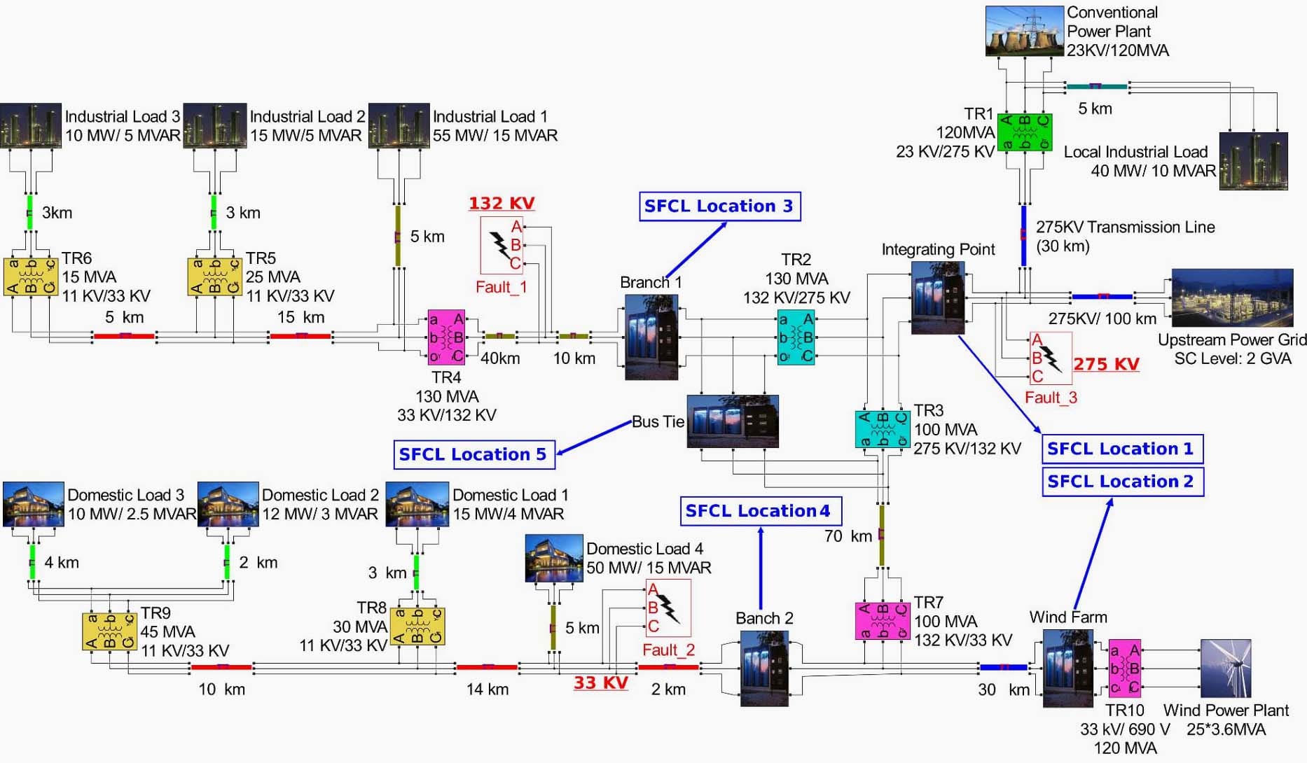
Figure 13 – Power system model based on the UK grid. Three prospective fault positions and five prospective SFCL locations are illustrated.
Go back to the Contents Table ↑
10. The ideal fault current limiter
The ideal fault current limiter should be invisible to the system in which it is installed except the short-circuit conditions it is designed to operate under. The ideal limiter should have the following characteristics:
- It should have a zero impedance and zero active and reactive power losses under normal unfaulted system conditions.
- It should detect, discriminate and respond to all types of short-circuit faults in less than 1 or 2 ms.
- When it responds, it should insert a very high limiting impedance to limit current flow. A mainly inductive impedance may be preferred in higher voltage networks although resistive limiters have the benefit of quickly suppressing the dc fault current component.
- It should automatically and quickly recover once the fault has been removed ready for another current limiting operation.
- It should be capable of performing successive current limiting operations without replacement.
- It should cause no unacceptable overvoltages or harmonics in the power system.
- It should have no adverse impact on power system protection performance.
- It should be highly reliable and fail-safe.
In practical installations, such an ideal limiter is not achievable and various design compromises have to be made.
Go back to the Contents Table ↑
11. Applications of fault current limiters
There are many different possible applications of fault current limiters in low, medium, high and extra high voltage power networks as well as in industrial power systems. The most efficient, in terms of fault current reduction, and economic method is chosen depending on network and substation specific factors.
A brief summary of the main applications is given below.
Figure 14 illustrates a case where the solid coupling of the 132 kV (110 kV) busbar is not possible due the short-circuit ratings of connected circuit-breakers being exceeded. The busbar is split into two sections which are connected by a fault current limiter.
Figure 14 – Fault current limiter used to couple substation busbars at 132 kV (110 kV)
The limiter’s impedance is chosen in order to reduce the short-circuit infeed from one side of the limiter for a fault on the other side, and vice versa, to well within switchgear ratings. For sufficiently large limiter impedance, the majority of the fault current on either side of the limiter is supplied through the transformers from the higher voltage network.
Figure 15 illustrates an extra high voltage substation with a significant amount of connected generation where the substation cannot be operated solid because the available short-circuit currents will exceed various switchgear and substation infrastructure ratings.
Figure 15 – Fault current limiter used to couple substation busbars at extra high voltage levels

Busbar splitting through a fault current limiter is quite effective in limiting the short-circuit current magnitude to well within switchgear and substation infrastructure ratings.
Figure 16 illustrates a fault current limiter application in series with a transformer in a high-to-medium voltage substation. The limiter acts to limit transfomer fed short-circuit currents for faults on the medium voltage substation.
Figure 16 – Fault current limiter in high-to-medium voltage transformer circuit
Figure 17 illustrates a fault current limiter application in series with a generator–transformer circuit. The limiter acts to limit the short-circuit current infeed from the generator for faults on the high voltage substation and the generator terminals.
Figure 17 – Fault current limiter in series with a generator–transformer circuit
Figure 18 illustrates a fault current limiter application in series with a generator–unit transformer that supplies the power station auxiliaries. The
limiter acts to limit the short-circuit infeed from the generator and the grid via the unit transformer for faults on the unit board and lower voltages within the auxiliary system.
Figure 18 – Fault current limiter in series with unit transformer supplying power station auxiliaries

Figure 19 illustrates a fault current limiter application in series with circuit feeders that export power from a large concentration of generation plant located at one or several locations.
Figure 19 – Fault current limiter in series with exporting circuits connecting large concentration of generation
Figure 20 illustrates the connection of a generator through a fault current limiter to a medium voltage grid to limit the generator’s short-circuit contribution to faults within this grid.
In this example, the limiter serves as an alternative to a transformer (and switchgear) connection to the high voltage grid.
Figure 20 – Fault current limiter facilitating the connection of a generator to a local grid
Figure 21 illustrates fault current limiters in series with low impedance transformers and medium voltage substation busbars coupled via a resistive superconducting fault current limiter.
Coupling the busbar sections through a superconducting fault current limiter, or ideally one that has a very low unfaulted impedance, increases the available short-circuit level at the busbar supplying the fluctuating load and improves the supply voltage quality.
Figure 21 – Fault current limiters that limit fault currents and improve supply voltage quality

Go back to the Contents Table ↑
Sources:
- Power Systems Modelling and Fault Analysis by Nasser D. Tleis
- Neutral Earthing Resistor by Captech
- Superconducting fault current limiters by Siemens
- Implementation of Resistive Type Superconducting Fault Current Limiters in Electrical Grids: Performance Analysis and Measuring of Optimal Locations by X. Zhang, H. S. Ruiz, Z. Zhong, and T. A. Coombs


Hello, please send me the pdf file of Short-circuit fault current limiters published in your webpage.
Great information ℹ️
This is an amazing the EEP