
Estimated Study Time: 6 minutes
Single-phase loads distribution
All single-phase loads, especially those with non-linear characteristics, in an electrical installation with a three-phase supply should be evenly and reasonably distributed among the phases.
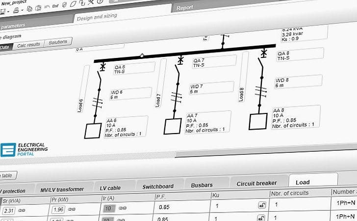 Balancing of single-phase loads to achieve energy efficiency (on photo: Ecodial network calculation tool developed by Schneider Electric)
Such provisions are required to be demonstrated in the design for all three-phase 4-wire circuits exceeding 100A with single-phase loads. The maximum unbalanced single-phase loads distribution, in term of percentage current unbalance shall not exceed 10%.
The percentage current unbalance can be determined by the following expression:
Iu= (Id × 100) / Ia
Where:
- Iu – percentage current unbalance
- Id -maximum current deviation from the average current
- Ia – average current among three phases
Unbalanced distortion
The adverse effects of unbalanced distortion on the power distribution system include:
- Additional power losses and voltage drop in the neutral conductors
- Causing unbalanced 3-phase voltages in the power distribution system
- Reduced forward operating torque and overheating of induction motors
- Excessive electromagnetic interference (EMI) to sensitive equipment in buildings
- Additional error in power system measurement
All single-phase loads are potential sources of unbalanced distortion.
They should be carefully planned at design stage for balancing, even though the random connection and operation of large number of small rating single-phase loads on the final circuits will tend to cancel their unbalance distortion effect in the main and sub-main circuits.
A 10% unbalanced phase current in a 3-phase 4-wire power distribution system with an average phase current of 100A (Figure 1) would produce a neutral current of about 17A and increase the total copper loss by about 1%.
The combination effect of 10% unbalanced and 30% THD phase currents (Figure 2 below) on the same circuit would produce a neutral current almost the same magnitude as the phase current resulting in much higher losses in a 3-phase 4-wire power distribution system.
Voltage level variation and unbalanced voltage caused by unbalanced distortion of single-phase loads are some of the voltage deviations which can affect motor operating cost and reliability. The published 3-phase induction motor characteristics are based on perfect balanced voltages between phases.
The magnitude of these ill effects is directly related to the degree of voltage unbalance. The adverse effects of unbalanced voltage on 3-phase induction motor operation comes from the fact that the unbalanced voltage breaks down into the positive sequence component and the opposing negative sequence component.
The positive sequence component produces the wanted positive torque. This torque is generally of less magnitude than the normal torque output from a balanced voltage supply and with somewhat higher than normal motor losses, because the positive sequence voltage is usually lower than rated voltage.
The negative sequence component produces a negative torque, which is not required. All the motor power that produces this torque goes directly into the loss that must be absorbed by the motor. By increasing the amount of unbalanced voltage, the positive sequence voltage decreases and the negative sequence voltage increases. Both of these changes are detrimental to the successful operation of motor.
Positive (E+ve) and negative (E-ve) sequence voltages can be calculated by the symmetrical components relationship as:
Where:
- ER, EY and EB are the original unbalanced voltages for red, yellow and blue phases and
- a = -1/2+j√3/2.
The application of negative sequence voltage to the terminal of a 3-phase machine produces a flux, which rotates in the opposite direction to that produced by positive sequence voltage. Thus, at synchronous speed, voltages and currents are induced in the rotor at twice the line frequency.
The application of negative sequence voltage can therefore affect torque, stator and rotor copper losses, rotor iron losses and consequently machine overheating. It is interested to note that harmonic voltages of the 5th, 11th, 17th, etc. order are also negative sequence and would produce similar adverse effect as unbalanced voltages.
Reference // Guidelines on Energy Efficiency of Electrical Installations – Electrical and Mechanical Services Department – The Government of the Hong Kong – Special Administrative Region
Related electrical guides & articles


Edvard Csanyi
Hi, I'm an electrical engineer, programmer and founder of EEP - Electrical Engineering Portal. I worked twelve years at Schneider Electric in the position of technical support for low- and medium-voltage projects and the design of busbar trunking systems.I'm highly specialized in the design of LV/MV switchgear and low-voltage, high-power busbar trunking (<6300A) in substations, commercial buildings and industry facilities. I'm also a professional in AutoCAD programming.
Profile: Edvard Csanyi

I wonder where the 10% came from? Can you state a code for this?
I came across a product enabling on line balancing of Phase current, the real requirement of both the user and supply company.. suggest you may cover such methods.
i would like to interact with you on three phase four wire DT imbalances.
Hello,
Mr. Edvard Csanyi
Hope you doing great. The EEP is a great place to study. I appreciate your effort.
I have been looking for finding a relevant code or standard for permissible imbalance of load per phase. I had an understanding that it should not be more 10%, which is vetted by your this blog. But can you please help me by refereeing a code or standard supporting this.
Hows it going the info is super, I’ve been thinking if your not busy would you like to visit sometime, their is vast economic possibilities here for someone with your expertise and experience. Once again Thank You for your literature…
am interested in your news letters
thanks edvard .
_neutral : why is moving as phase
-real curve have noknow fonction witch is real fonction ex : u= f(x,t,constante) insteas for u theorique = sin(kt+constante.p)////