
Estimated Study Time: 9 minutes
Transformer protection
The degree of transformer protection provided depends to a great extent upon the size and functional importance of the unit. A further important factor is the economic aspect. The cost of protection for power transformers tends to be proportionally higher than the cost of protection for other items of plant.
 The basic protection schemes for 4 typical transformer types in power system
The most important you should note is that effects of thermal stress and electrodynamic forces must be reduced and that can be done only with carefully selected transformer protection that minimizes the time for disconnection in the event of a fault.
This technical article covers protection schemes of four typical transformer types:
- Distribution transformers
- Two-winding transmission transformers
- Station transformers (in power generating plants)
- Autotransformers for transmission
1. Distribution transformers
With distribution transformers the economic considerations are predominant, and the minimum protection is usually provided consistent with acceptable overall performance.
High speed protection is not always necessary, particularly for phase-faults as power system stability problems have rarely to be considered.
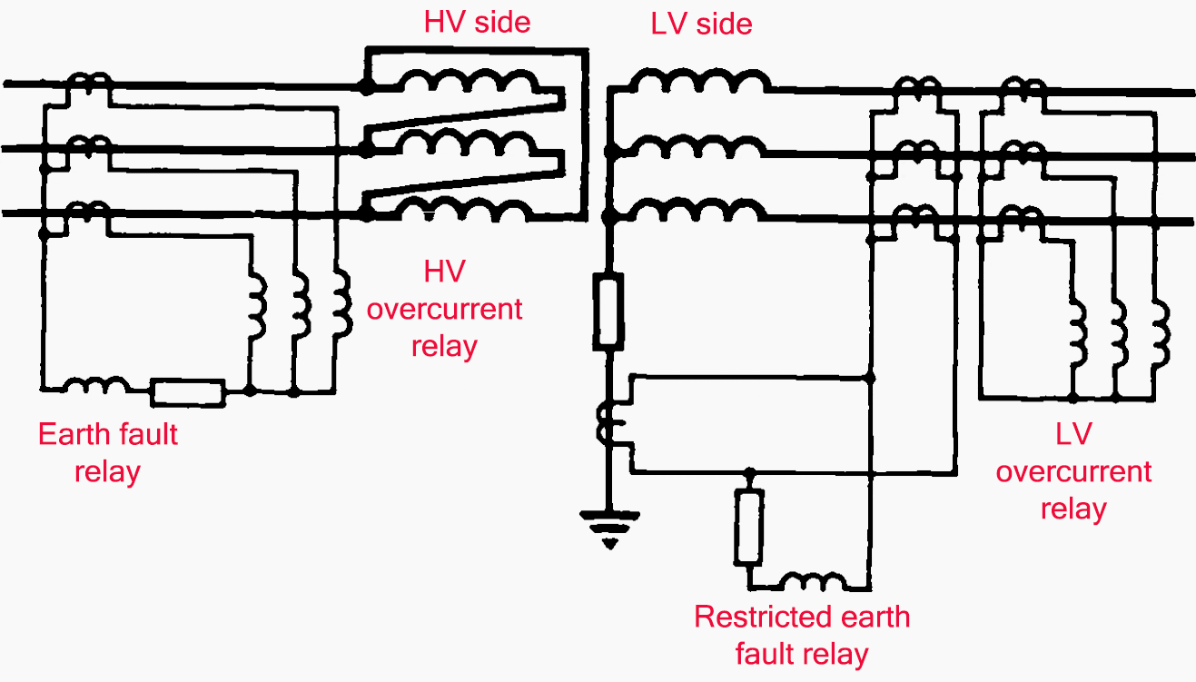
Larger distribution transformers are protected by overcurrent and earth-fault protection. Where fault current can be fed from HV and LV sides the overcurrent protection is usually fitted to both sides of the transformer.
Figure 1 shows a typical arrangement.
Larger distribution transformers may also have overall differential protection in which the restricted earth fault protection is incorporated. The protection of such transformers in practice may differ little from two-widing transmission transformers described in the next paragraph.
2. Two-winding transmission transformers
Economic considerations in the protection of transformers connected to the 132 kV, 275 kV and 400 kV grid system tend to be outweighed by the need for high speed fault clearance, necessary for system stability reasons, and the need to minimize fault damage.
To achieve high-speed discriminative fault clearance for both phase faults and earth-faults differential protection with HV and LV restricted earth fault is fitted.
The differential protection usually incorporates load bias and harmonic restraint features.
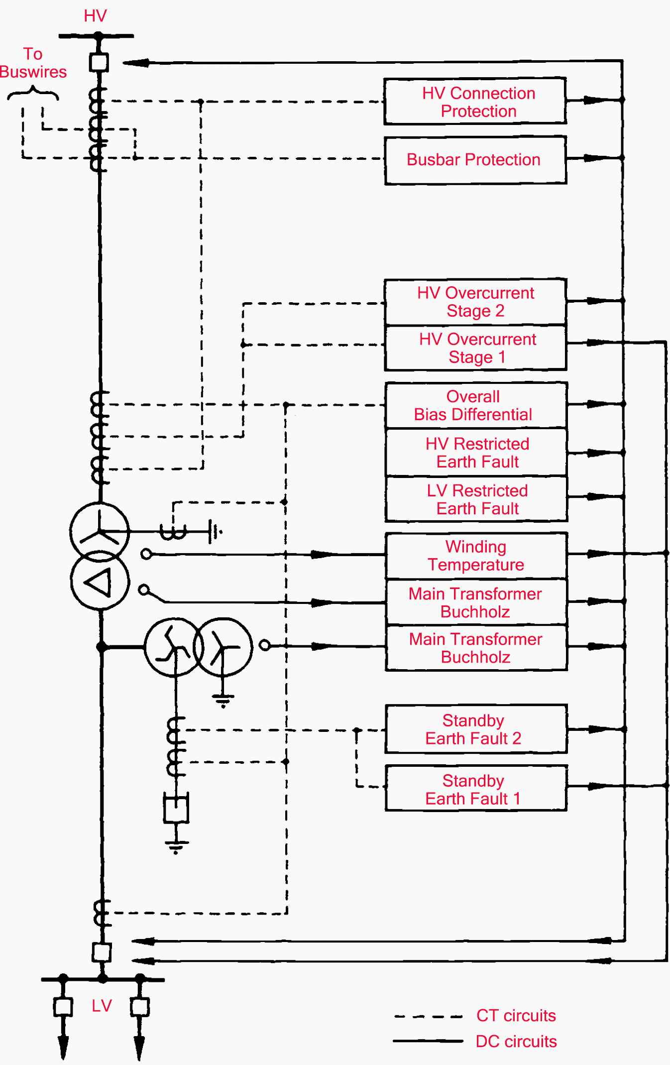
Gas- and off-actuated relays are fitted to both the main transformer and its associated earthing (auxiliary) transformer. Duplicate winding temperature instruments are fitted for starting the cooling, and for alarm and trip.
Back-up protection is provided by overcurrent relays and LV standby earth-fault relays (one or two stages).
A typical 132 kV grid transformer protection arrangement is shown in Figure 2 above.
On a single transformer installation the HV connections are normally included in the zone of the overall differential and balanced earth-fault protections. Where transformers are banked it is preferable to have separate overall differential and balanced earth-fault protection for each transformer, and a separate circulating current system for the protection of the h.v. interconnections. This requires current transformers in the transformer HV bushings.
Banked transformers will invariably be fitted with two stage standby earth fault protection.
3. Station transformers (in power generating plants)
At most major generating stations transformers are installed to provide a supply to the station auxiliaries from the grid system. Though their MVA rating may be comparatively low, these station transformers are important units, and their protection is governed by technical rather than economic considerations.
Station transformers normally have on-load tap changing, but forced cooling is not employed. The windings are usually star/delta/star, the HV winding being solidly earthed and the LV winding resistance earthed.
Since these transformers are connected to the grid system, internal fault currents can reach very high multiples of transformer rating (for example 300 times CT rating), and the protection arrangements must be capable of correct operation at these high currents.
The protection fitted to a station transformer is similar to that applied to a grid transformer except that winding temperature indicators may be omitted.
4. Autotransformers for transmission
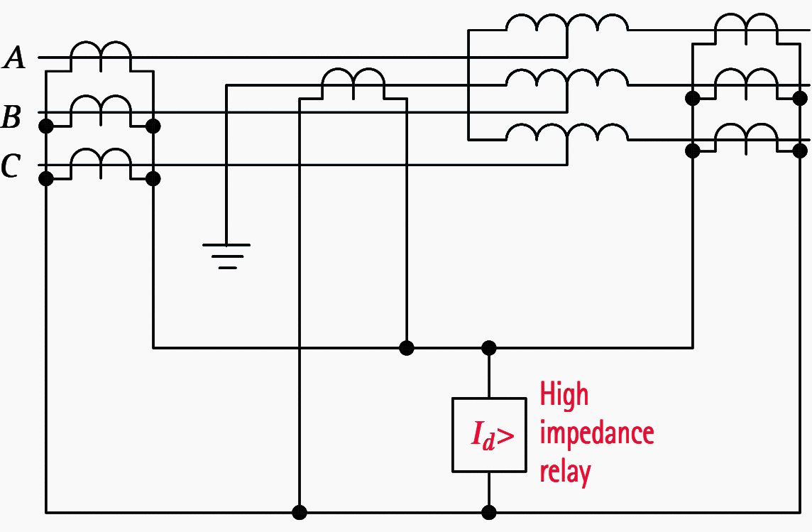
Autotransformers are used to couple EHV power networks if the ratio of their voltages is moderate. An alternative to Differential Protection that can be applied to autotransformers is protection based on the application of Kirchhoff’s law to a conducting network, namely that the sum of the currents flowing into all external connections to the network is zero.
If one neutral current transformer is used, this and all the line current transformers can be connected in parallel to a single element relay, thus providing a scheme responsive to earth faults only.
See Figure 3 below.
If current transformers are fitted in each phase at the neutral end of the windings and a three-element relay is used, a differential system can be provided, giving full protection against phase and earth faults.
See Figure 4.
This provides high-speed sensitive protection. It is unaffected by ratio changes on the transformer due to tap-changing and is immune to the effects of magnetizing inrush current.
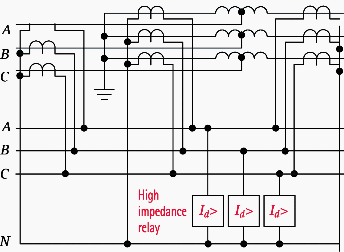
It does not respond to interturn faults, a deficiency that is serious in view of the high statistical risk quoted in Section 16.1. Such faults, unless otherwise cleared, will be left to develop into earth faults, by which time considerably more damage to the transformer will have occurred.
In addition, this scheme does not respond to any fault in a tertiary winding. Unloaded delta-connected tertiary windings are often not protected. Alternatively, the delta winding can be earthed at one point through a current transformer that energizes an instantaneous relay.
This system should be separate from the main winding protection. If the tertiary winding earthing lead is connected to the main winding neutral above the neutral current transformer in an attempt to make a combined system, there may be ‘blind spots’ which the protection cannot cover.
Sources:
- Protection of generators, transformers, generator-transformer units and transformer feeders by J.Rushton, revised by K.G.M.Mewes
- Network Protection And Automation, Protective Relays, Measurement & Control – Alstom Grid
Related electrical guides & articles


Edvard Csanyi
Hi, I'm an electrical engineer, programmer and founder of EEP - Electrical Engineering Portal. I worked twelve years at Schneider Electric in the position of technical support for low- and medium-voltage projects and the design of busbar trunking systems.I'm highly specialized in the design of LV/MV switchgear and low-voltage, high-power busbar trunking (<6300A) in substations, commercial buildings and industry facilities. I'm also a professional in AutoCAD programming.
Profile: Edvard Csanyi

Hi Edvard Csanyi sir, Excellence of your Knowledge and Great Help for Electrical Engineering Learner ,
I am surprised about the ample resources provided merely by this EEP portal.
I self K.Krishnarao work experience as faculty for Undergraduate engg students and a little bit of experience in low voltage electrical installation.
Here I am seeking help and guidance either at chargeable or just like you can provide information about from 11KV systems detailed electrical distribution upto the single load point that I need to know about designing details including helpful electrical software and also all other resources.
Awsome articl, but need more elaboration.
Capacitor cell repair procedure 4.8
200 var
Oil leak
And
Opening method inside the capacitor cell
Great articles
Good day author, please kindly send me a copy of this paper to my mail, or send me a link to download it. Thanks