
Estimated Study Time: 5 minutes
General about capacitor banks
As you already know, capacitor banks are normally used in medium voltage networks to generate reactive power to industries etc. Capacitor banks are, almost always, equipped with a series reactors to limit the inrush current.
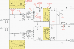
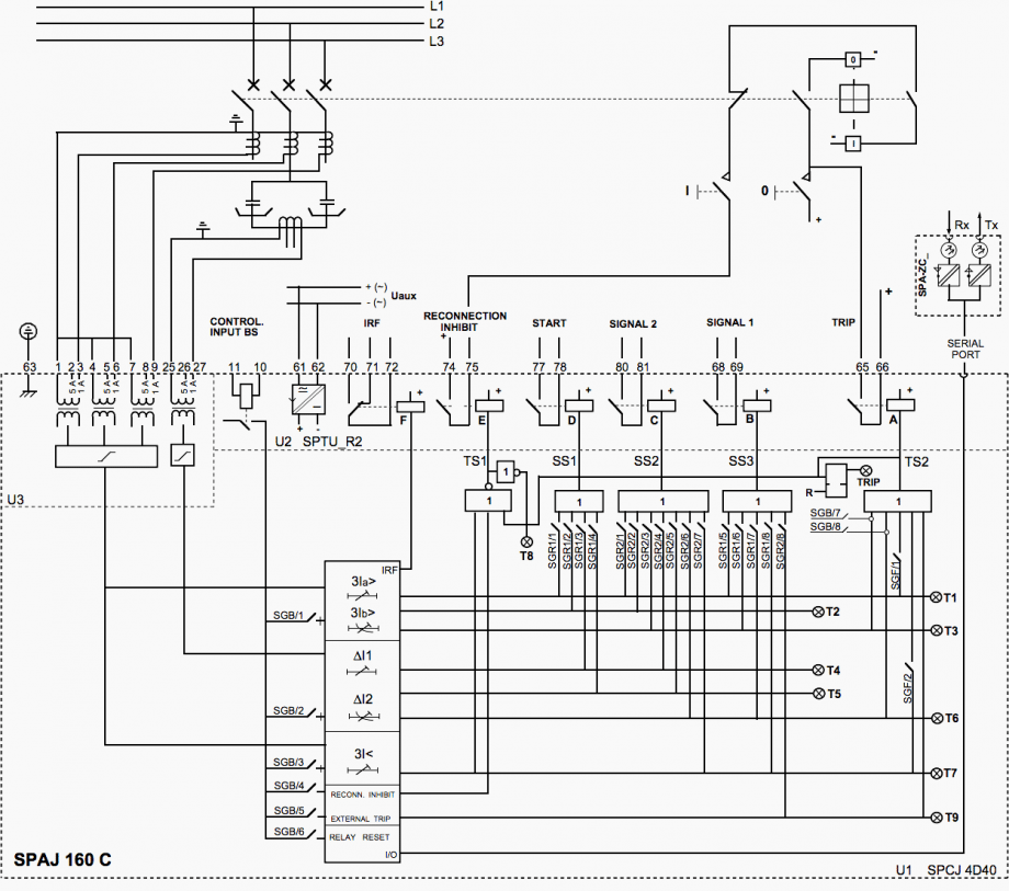 Complete connection diagram for the capacitor bank protection relay SPAJ 160 C with all the relay matrix and blocking/control input programming switches shown
Harmonic filters, for thyristor controlled reactors, are also variations of capacitor banks having the reactor inductance together with the capacitor capacitance tuned for series resonance at a certain frequency.
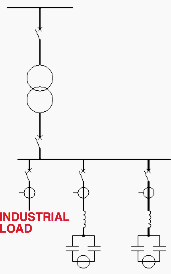
The tuning are purposely a little bit incorrect, in order not to get a too low impedance for the harmonic, to which it is tuned. The capacitor banks usually are connected in double Y-connection with the neutral of the halves connected.
The current between the two neutrals are supervised by an overcurrent (unbalance) relay.
Capacitor bank protection
1. Unbalance relay
This overcurrent relay detects an asymmetry in the capacitor bank caused by blown internal fuses, short-circuits across bushings, or between capacitor units and the racks in which they are mounted.
Each capacitor unit consist of a number of elements protected by internal fuses. Faulty elements in a capacitor unit are disconnected by the internal fuses. This causes overvoltages across the healthy capacitor units.
In normal service when all capacitor units are healthy the unbalance current is very small. With increasing number of blown internal fuses the unbalance current increases and the unbalance relay will give an alarm. The alarm level is normally set to 50% of the maximum permitted level.
The capacitor bank then should be taken out of service to replace the faulty units. If not the capacitor bank will be tripped when the maximum allowed unbalance current level is exceeded.
2. Capacitor bank overload relay
Capacitors of today have very small losses and are therefore not subject to overload due to heating caused by overcurrent in the circuit.
Overload of capacitors are today mainly caused by overvoltages. It is the total peak voltage, the fundamental and the harmonic voltages together, that can cause overload of the capacitors.
The capacitor can withstand 110% of rated voltage continuously. The capability curve then follows an inverse time characteristic where withstand is approximately 1 second -180%, 10 cycles -210%.
For example, ABB Transmit Oy have designed a relay that measures the current in the capacitor bank and transforms this into a voltage that corresponds to the voltage across the elements in the capacitor bank.
This relay is called SPAJ 160C and includes unbalance protection, overload protection and undercurrent relay. The undercur- rent function is used to prevent the charged capacitor bank to be reconnected when a short loss of supply voltage occurs.
The connection of the relay is shown in figure 2.
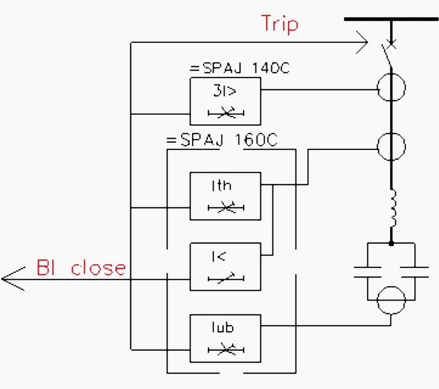
3. Short circuit protection
In addition to the relay functions described above the capacitor banks needs to be protected against short circuits and earth faults. This is done with an ordinary two- or three-phase short circuit protection combined with an earth overcurrent relay.
Reference // Protection Application Handbook by ABB
Related electrical guides & articles


Edvard Csanyi
Hi, I'm an electrical engineer, programmer and founder of EEP - Electrical Engineering Portal. I worked twelve years at Schneider Electric in the position of technical support for low- and medium-voltage projects and the design of busbar trunking systems.I'm highly specialized in the design of LV/MV switchgear and low-voltage, high-power busbar trunking (<6300A) in substations, commercial buildings and industry facilities. I'm also a professional in AutoCAD programming.
Profile: Edvard Csanyi

Hi Edvard,
i was wandering why voltage protection for capacitors are so rare. is there a reason for this?
Dear Eng
Please I need More information about current Differential protection for 132KV Capacitor Bank.
thanks
Thank you very much for this useful information.
Dear author,
Thank you very much for the valuable information you shared with others
Best regards
Sharief Massoud
I was a good article for the “ordinary” electrical engineer who still does not understand overload or undercurrent etc.in a capacitor
Helpful
Good job I like this
You could also use an inrush current limiter to prevent high inrush currents at the switching ON moment.
Prevents burned switch contacts and helps increasing life time expectation of capacitors.
These are available in single phase and 3-phase versions, with assymetry and phase error alarms.
Can send datasheets upon request.
Please send inquiry to [email protected]
Good job.
For large capacitor banks with several groups units, you must foresee overvoltage protection, as well.
In this case, the individual units are protected by fuses and series connected.
If two or more fuses blow, the voltage across the remaining will be larger than 10%. This will substantially reduce the units lifetime.
But how to detect this overvoltages?
You must connect a voltage differential relay between a PT connected to the line voltage and a PT connected to a point on 10% of the line voltage. This is achieved by using a 10% rated voltage divider. S&C had a device like that which was nothing more than a resistor.
Setting must follow the above conditions.
Use, for instance, SEL 287