
Estimated Study Time: 7 minutes
Introduction to 3-ph motor
This article will deal with those concepts of 3 phase induction motor which are essential prerequisite for proper selection, procurement, installation and maintenance of the same.
Before any actual discussion on motor is started It will better to have a comparison of starting behavior of induction motor and transformer because as per the equivalent circuit representation a 3 phase induction motor is generalized transformer.
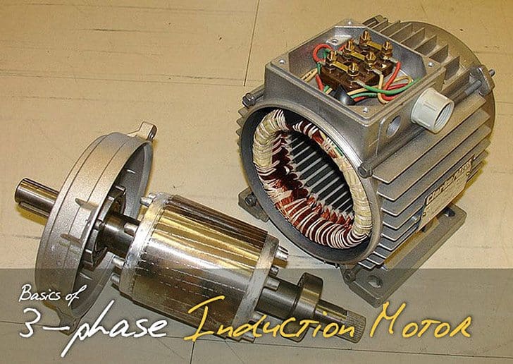
It is assumed that readers are already familiar with the elementary concept of principle of operation and construction of three phase induction motor.
Induction motor is a generalized transformer. Difference is that transformer is an alternating flux machine while induction motor is rotating flux machine. Rotating flux is only possible when 3 phase voltage (or poly phase) which is 120 degree apart in time is applied to a three phase winding (or poly phase winding) 120 degree apart in space then a three phase rotating magnetic flux is produced whose magnitude is constant but direction keeps changing. In transformer the flux produced is time alternating and not rotating.
There is no air gap between primary and secondary of transformer where as there is a distinct air gap between stator and rotor of motor which gives mechanical movability to motor. Because of higher reluctance ( or low permeability) of air gap the magnetizing current required in motor is 25-40% of rated current of motor where as in transformer it is only 2 -5 % of rated primary current.
In an alternating flux machine frequency of induced EMF in primary and secondary side is same where as frequency of rotor EMF depends on slip. During starting when S = 1 the frequency of induced EMF in rotor and stator is same but after loading it is not.
Other difference is that the secondary winding and core is mounted on a shaft set in bearings free to rotate and hence the name rotor.
If at all secondary of a transformer is mounted on shaft set at bearings the rate of cutting of mutual magnetic flux with secondary circuit would be different from primary and their frequency would be different. The induced EMF would not be in proportion to number of turns ratio but product of turn ratio and frequency. The ratio of primary frequency to the secondary frequency is called slip.
Any current carrying conductor if placed in magnetic field experience a force so rotor conductor experience a torque and as per Lenz’s Law the direction of motion is such that it tries to oppose the change which has caused so it starts chasing the field.
Power flow diagram of induction motor
Stator input electrical power = A
Stator losses = B
Rotor losses = C
Mechanical output = P
A – ( B + C ) = P
Roughly B= 0.03A, C= 0.04A
A – 0.07A = P
0.93A = P, Hence efficiency = (P/A) x 100 = 93%

Why LT motors are delta connected and HT motors are star connected?
Reason is techno commercial.
- In star, phase current is same as line current. But phase voltage is 1/1.732 times line voltage. So insulation required in case of HT motor is less.
- The starting current for motors is 6 to 7 times full load current. So start-up power will be large if HT motors are delta connected. It may cause instability (voltage dip) in case small Power system. In starred HT motor starting current will be less compared to delta connected motor. So starting power is reduced. Starting torque will also be reduced. (It will not be a problem as motors are of high capacity.)
- Also as current is less copper (Cu) required for winding will be less.
- LT motors are delta connected.
- Insulation will not be problem as voltage level is less.
- Starting current will not be problem as starting power in all will be less. So no problem of voltage dips.
- Starting torque should be large, as motors are of small capacity.

1. In case it is having star delta starter than they are started as Star connected motor.
2. After it attains 80% of synch speed the changeover takes place from star to original configuration delta.
3. In star the voltages across the windings are lesser that is 1/1.732 times that available in delta so current is limited.
4. When it goes to delta again voltage is full line voltage so current increase even though it is lesser than the line current it remains higher than the line current drawn in star connection at reduced voltage. So cables for motor are sized for this current that is what it draws in delta connection.
References:
1. NEMA MG-1.
2. Industrial Power Engineering and Application Hand Book by K C Agarwaal.
3. Industrial Power System Hand Book by Shoaib Khan.
4. Theory and Calculation of Alternating Current Phenomena by Charles Proteus Steinmetz
5. Motor protection relay (MM30) manual from L&T
Related electrical guides & articles


Asif Eqbal
Bachelor of Engineering in Electrical & Electronics engineering, from Manipal University, (Karnataka), India in 2006. Presently involved in the design of EHV outdoor substation and coal fired thermal power plants for more than seven years. Motto of joining EEP as a contributor is to share my little engineering experience and help the budding engineers in bridging the conspicuous gap between academics and Industrial practice. “If you have knowledge, let others light their candles with it, so that people who are genuinely interested in helping one another develop new capacities for action; it is about creating timeless learning processes".Profile: Asif Eqbal

Have an idea to invent an electric power generating machine but I need you assistance, thanks ,please you can whatsap me on this line for discussion +2348034681128
sir,
please explin how much i set the derived earth fault both idmt and instantaneous .600 kw 3.3kv induction motor .there are a relay siemens argus 7sr17
What happens if we use silicon steel core in induction motor for path of flux instead of air gap?
Hello;
I want to know how we can defined the turn ration between the primary and secondary in induction motors.
thanks
please guide me that how much an LT 3 phase induction motor will consume current in star configuration at start
for example we have a 37W/50 hp motor so what will be starting current consumption for this motor and motor is connected in star delta configuration. i m confused it will be six times or 3 times of the rated current.
What happens if we use silicon steel core in induction motor for path of flux instead of air gap?
hey!!
Can anyone tell me, how to find the winding data of fresh stator. if slots & HP is known
Hi Asif,
There’s a slight misunderstanding in your explanation on the reason for Star and Delta connections.
In fact the reason we use Star connection on higher voltage machines is to drop the Volts per pole.
The motor performance doesn’t need to change at all because the turns per coil and conductor sizes are changed to suit the changed phase volts.
Star connection reduces the volts per phase, so in design, the turns are reduced proportionately and the conductor size increased proportionately.
That means the flux density in the iron remains the same, so shaft torque and starting curve is the same.
There is no real commercial advantage either. There is the same total amount of copper in the slot.
Could you please explain/ draw how to connect a three pole two way with off rotary switch to a three phase motor in order to obtain two speeds with off between.
Hllo
sir
give me ac motor winding data calculator and ac motor winding data list 0.5 hp to350hp
Can you please explain Steinmetz equivalent circuit of induction motor, mainly the relationship between frequency of supply and equivalent resistance across the rotor side??
If there any book or material in which mpm, cpm , rpm equations for induction motors used in automation industry are given?
Take a look at the section ‘Industry and automation guides’:
https://electrical-engineering-portal.com/download-center/books-and-guides/automation-control
hello sir
in our site we are having a ht induction motor .in that there are two terminal boxes one is for 6.6kv supply connected in star and other is 3.3kv supply terminal box connected in delta ,,how in one winding there are two connections ? and do we need to change star connection if we use delta?
Sir I think starting c/n of 3 phase induction motor around 1.5 times full load current..
given data;
supply voltage 400v
3 phse induction motor star connected
per phase rotor resistance referd to stator: 0.5 hom
freeqency 50
4 pole , 1440 rpm sqirrel cage
coupled load torqe;20
remaning neglected
WHAT ISsteady state speed in radians per second
Sir my question is , is it necessary for the rotor and stator to have same number of poles in order to run?
just 1st how many pole each rotor and stator.
but, i think stator have pole & do’t rotor.
rpm= 120*F./no. of pole
Automatically in 3 phase motor the rotor assumes same pole of stator
Power Electrical Engeering information
Has anyone put a third coil around the secondary coil? Completely naive question; (I’m an IT guy). C
urrent in on the primary. Current in on the tertiary. What does the secondary do?
Current on primary; motion on secondary. What happens to the tertiary?
Someone must have put two currents in (1&3). What happens?
Please add me in your website as I am good fan of you
When IM starts we have high inrush current, but how this current comes to normal value when motor works at or around rated speed?
And is their any difference between full load current and name plate rated current?
hii ; great post
could you tell me, magnetizing current is higher in transformer or in induction motor ?
Hi, greetings.
magnetizing current is lower in a transformer, and its a lot lower. In transformers, magnetizing currents its about 4% of the nominal current, but… In induction motors its about 30%.
This difference is because the high reluxtance value, just like the autor said in the paper.
Hope to be usefull.
TO Ahmedelwake: I think magnetizing current is less in case of transformers because they do not have an air-gap unlike induction motors!
Magnetizing current is higher in Induction motor as compared to transformer. The reason is that the flux in motor faces much more reluctance due to air gap present between stator and rotor as compared to transformer flux which has less reluctance due to continuous magnetic core. So to overcome this reluctance and magnetize the rotor, magnetizing current is much higher in Induction motor
Hi!
Why induction motor draws 6-7 times of full load current during starting using DOL?
In three phase induction motor the magnitude of induced EMF in rotor depends upon on the slip of induction motor.This induced EMF effectively decides the magnitude of rotor current. Rotor current in running condition is given by:
I2r = sE2/√R22 + (sX2)2
During starting speed of motor is zero and hence slip is unity. So magnitude of rotor induced EMF is very large at start. As rotor conductors are short-circuited, the large induced EMF circulates very high current through rotor at start.The condition is exactly similar to transformer secondary short-circuited and excited by rated voltage. The current through shorted secondary is very large so primary also draws a very high current. Similarly in induction motor when there is high current in rotor stator also draws high current from supply.
A good post, but you should define LT and HT in the 2nd half of the article. I assume you mean Low Torque and High Torque, but it is unclear.
LT and HT meant here low tension and high tension or low voltage and medium voltage. Intended to highlight the difference in winding configuration of motor connected by low voltage supply (less than 400V) and motors connected to medium voltage supply (more than equal to 3.3kV)
sir want 2 ask what is required more to start an induction motor
1 phase current
2 phase voltage
3 line voltage
4 line voltage
hi
i am shahbazi,and need to documents for number starting motor6.6 in perhore
in three phase induction motor when rotor rotate ….in that rotor have a current and voltage….but not produced in shaft why…
Mr Herry,
Stator rest on motor frame, after air gap there is rotor which is mounted on shaft and shaft rests on bearing and bearing in turn rest on frame.
Rotor voltage at any speed (running condition) = Slip times the rotor stand still voltage.
Frequency of induced voltage in rotor = Slip times supply voltage frequency
During stand still condition voltage induced in rotor = (Stator induced EMF -stator losses) x turn ratio of winding x distribution factor x pitch factor of winding.
Voltage is induced in rotor as per above mentioned expressions. Since during running condition rotor voltage is very small that is slip (1-2%) times the stand still stator voltage hence rotor voltage and consequently the shaft voltage is negligible. Only in standstill (slip being 1 during stand still) condition this voltage is of concern.
In all conditions (stand still and running) significant shaft voltage & currents may exist in VFD/VSD application, large LT and for HT motors of 2000 kW and above, using circular laminations and all motors with segmented laminations. As per IEC-34-17 shaft voltage should not exceed 500 milliVolts. Shaft voltage in induction depends upon the following:
1. Design of motor
2. Capacitance between rotor and stator as well rotor and frame
3. Configuration of mains supply
4. Voltage transients on motor terminal
5. Magnetic field caused by asymmetries
6. Dielectric leakages in HT motors of 2.4 kV and above
This can be prevented by grounding one of the bearings to prevent the leakages. The bearing insulation is thus determined by the manufacturer while checking the shaft voltage at the works. This forms a routine in-house test for all HT and large LT motors. To detect shaft currents, the normal procedure of leading manufacturers is to measure the shaft voltage end to end, with a full voltage applied to the motor terminals.
If this is 300-350 mV or more, it will indicate that the bearings require insulation. As per Indian standards measurement of bearing current is done for motors above 1000kW.Provision is made to measure the bearing insulation resistance of insulated bearings without disassembling the motor or removing it from its base. All motors used for VFD applications have insulated bearings
In addition to my previous reply please note that rotor core are laminated with insulated sheets so voltage induced in rotor can get induced in shaft as both are in contact but only a very small amount of rotor voltage gets induced in shaft that is as good as leakage voltage.
could you clearly explain the cable sizing for star delta starter and also give clear diff b/w dol and star delta starter