
Continued fro second part – Basics of 3-phase Induction Motor (part 2)
Technical data to be specified by purchaser before purchasing a 3 phase induction motor:
Site Conditions
| No. | Technical data to be specified | Data |
| 1. | General data about ambient temperature and altitude: | |
| 2. | Area Classification: | |
| 3. | Temperature Class: | |
| 4. | Gas Group: | |
| 5. | Type of Protection: |
Basic Data
| No. | Technical data to be specified | Data |
| 1. | Supply System: | 415V 3 Ph 50 Hz |
| 2. | Neutral: | |
| 3. | Cooling method (Any one of the below): TENV Totally Enclosed, Non-Ventilated/ TEFC Totally Enclosed, Fan Cooled/TETC Totally Enclosed, Tube Cooled/ TEAAC Totally enclosed, Air to Air cooled /CACA Totally Enclosed, Air circuit machine with air cooler/CACW Totally Enclosed, Air circuit machine, water cooled air cooler. | |
| 4. | Degree of Enclosure Protection: | |
| 5. | Continuous Rating: | |
| 6. | Service Factor: | |
| 7. | Synchronous Speed: | |
| 8. | Insulation Class: | |
| 9. | Max. Permitted Temp Rise: | Class 77 Deg Celsius |
| 10. | Direction of Rotation (Any one of the below): CW/CCW/Bi-Dir. | |
| 11. | Method of Starting: | |
| 12. | Winding Connection: | |
| 13. | Neutral Terminals req.: | |
| 14. | Shaft Orientation (Any one of the below): Horizontal/Vertical | |
| 15. | Mounting: Foot/Flange | |
| 16. | Slide Rails Required: | |
| 17. | Heater Required: | |
| 18. | Heater Voltage: | (Motors rated below 37 kW shall employ 24V AC direct winding) |
| 19. | Drain Required: | |
| 20. | Breather Required: | |
| 21. | Maximum Noise Level: | 85dB (A) at 1m |
| 22. | GD2 (Pump + Coupling) = | |
| 23. | Winding temperature monitoring:
| |
| 24. | Bearing temp monitoring:
| |
| 25. | Differential CT’s: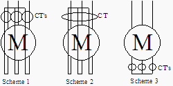 If yes then:
| |
| 26. | Cable Type:
| |
| 27. | Heater Terminal Box Entry: | |
| 28. | RTD/Thermocouple Terminal Box Entry: | |
| 29. | CT Terminal Box Entry: | |
| 30. | Motor Starter Protective System (Any one of the below):Fuses+Contactor+OLR/ Circuit Breaker with overload, earth fault, undercurrent, Phase Unbalance, under voltage, Stall, Limit No. of Starts, over current | |
| 31. | Prospective System Fault Current: | 50 kA (RMS SYM.) |
| 32. | Surge Protection Required: | |
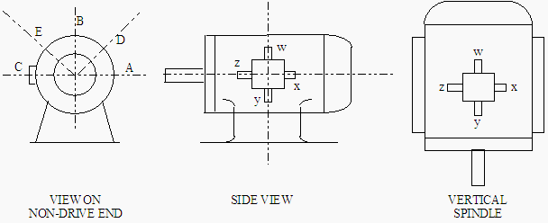
Technical data to be specified by manufacturer before selling a 3 phase induction motor
| No. | Technical data to be specified | Data |
| 1. | Standard: | |
| 2. | Full Load Current (FLC): | |
| 3. | Starting Current: | |
| 4. | Efficiency (100/75/50%): | |
| 5. | Power Factor (100/75/50%): | |
| 6. | Power Factor (Starting): | |
| 7. | Full Load Torque (FLT): | |
| 8. | Starting Torque: | % FLT |
| 9. | Minimum Accelerating Torque (Motor & Load) @ 80%Volts: | % FLT |
| 10. | Pull-Out Torque: | % FLT at %SLIP |
| 11. | Locked Rotor Withstand Time:
| |
| 12. | Run-Up Time (Motor & Load):
| |
| 13. | Insulation Class & Temp Rise above Design Ambient: | |
| 14. | Maximum No. of Successive Starts: | |
| 15. | Max. No. of Starts in 1 Hour: | |
| 16. | Rotor Resistance (ac) @ 20°C pu Motor VA (Locked Rotor / Rated Load) | |
| 17. | Rotor Reactance @ 20°C pu Motor VA (Locked Rotor / Rated Load) | |
| 18. | Stator Resistance (ac) @ 20°C pu Motor VA (Locked Rotor / Rated Load) | |
| 19. | Stator Reactance @ 20°C pu Motor VA (Locked Rotor / Rated Load) | |
| 20. | Stator Leakage Reactance @ 20°C pu Motor VA (Locked Rotor / Rated Load) | |
| 21. | Magnetizing Resistance @ 20°C pu Motor VA | |
| 22. | Magnetizing Reactance @ 20°C pu Motor VA | |
| 23. | Torque / Speed Characteristic | |
| 24. | Current / Speed Characteristic | |
| 25. | Heating Time Constant: | |
| 26. | Cooling Time Constant: | |
| 27. | Bearing Type: Ball/Roller/Sleeve/Antifriction | |
| 28. | Lubrication: Oil/Grease | |
| 29. | Oil/Grease | |
| 30. | Cooling System: | |
| 31. | Rotor End float: +mm -mm | |
| 32. | Rotor End-Play: +mm -mm | |
| 33. | Rotor Air Gap: mm | |
| 34. | Moment of Inertia GD² (Motor & Load): kgm² Referred to motor (including gearbox where applicable) | |
| 35. | Weight of Motor: kg | |
| Noise Level: dB @ m |
What precautions are to be taken while designing of foundation of rotating machines (Here 3 Phase induction motor)?
General
- Description of driving and driven machinery,
- Operating speed or speed ranges,
- Number and arrangement of cylinders,
- Distance between axis of main shaft of the machine and the top face of foundation,
- Maximum rated output,
- Gear box ratio where applicable, and
- Maximum operating temperature in the bases of the machine.
For Static Design
- A detailed loading diagram comprising plan, elevation and section showing details of communication and point of all loads on foundation.
- A detailed drawing showing the position and size of mounting feet and details of holding down bolts.
For Dynamic Design
- Details of out of balance forces and couples shall be given, together with associated frequencies for all possible modes of vibration for driving and driven machinery. These include the following:
a) External forces,
b) External primary couples,
c) External secondary couples, and
d) Harmonic torques. - Mass moments of inertia of driving and driven machine about three principal axes shall be indicated.
- Additional information relating to specific machines, as given below, shall be provided where necessary:
a) Loads due to dynamic short circuit conditions, and
b) Loads due to an abnormal sudden stoppage. - Where it is found necessary to use anti-vibration mountings, the type and positions be indicated.
Data on Ground and Site Conditions
The following soil data shall be known:
- Soil profile and soil characteristics up to a depth at least three times the expected mean plan dimension of the foundation which can be taken as the square root of the expected area, or hard strata.
- Soil investigation to the extent necessary in accordance with IS: 1892-1979 and for the determination of dynamic properties of soil in accordance with IS: 5249-1977.
- The relative position of the water table below ground at different times of the year.
Frequency ratio
Wherever possible the natural frequency of the foundation soil-system shall be higher than the highest disturbing frequency and the frequency ratios shall not be normally less than 0.4.Where this is not possible, the natural frequency of the foundation-soil system shall be kept lower than the lowest disturbing frequency. The frequency ratios in such cases shall not be lower than 1.50.
While the above criteria shall be applied to all possible modes of vibration, it may be permitted to operate machines closer to the resonance in certain modes of vibration provided the resulting amplitudes do not exceed the permissible limit.
Even though machine may be balanced, minor disturbing forces can occur due to manufacturing tolerances and other causes, for sensitive installations, the frequencies arising from these may have to be considered.
Permisible Amplitudes
Limitations of Vibration Amplitude to Avoid Damage to Machinery
This shall be specified by the manufacturer and shall in no cases be exceeded. Where no specific limit has been stated by the manufacturer, it may be taken that foundation satisfying the following amplitude criteria shall provide a satisfactory base for machinery.
Limitations of Vibration Amplitude to Avoid Damage to Machinery
the damage in neighboring buildings due to resonance will be negligible if the amplitude vibration of the foundation is less than 200 microns at frequencies below 20 Hz, where the disturbing frequency exceed 20 Hz, a lower amplitude may be necessary for certain installations.
Limitation of Vibration Amplitude to Avoid Discomfort of Persons
for low speed machines, it is unlikely that foundations which satisfy the previous point will produce vibrations of sufficient amplitude to be disturbing to persons. In special cases where there are particular reasons to avoid discomfort to personnel
Limitations of Amplitude to Avoid Settlement
for most soil types, foundations for low speed machines designed to limiting amplitude of 200 microns will not suffer undue settlement due to dynamic loads. In case of some soils like loose sands and silts in conjunction with high water table, there is a possibility of significant settlement to occur. In all such cases, it shall be preferable to consolidate the soil underneath the foundation.
Anti-Vibration Mountings
Where it is found to be impracticable to design a foundation consisting of a simple concrete block resting on the natural soils to give satisfactory dynamic characteristics, it may be possible to reduce the transmitted vibrations to acceptable levels by means of anti-vibration mounting. Depending upon the nature of the machinery and the installation, the anti-vibration mounting may be used:
a) Between machinery and foundation, and
b) Between a foundation block and a supporting system.
Free vibration analysis
Free vibration analysis shall be carried out to calculate the natural frequencies and mode shapes of the foundation. The highest natural frequency calculated should be at least 10 percent higher than the operating frequency of the machine. Damping may be neglected for the purpose of free vibration analysis.
Frequency criteria
The following frequency criteria shall be checked:
The fundamental natural frequency shall be at least 20perccnt away from the machine operating speed.
That is, fn < 0.8 fm or fn > 1.2 fm
Where
fn = fundamental natural frequency of the foundation, and
fm = operating speed of the machine.
However, it is preferable to maintain a frequency separation of 50 percent.
Conclusion
The foundation of any rotating electrical machine operating at 50 Hz should be such that the natural frequency of vibration is either less than 40 Hz or greater than 60 Hz.
References:
1. NEMA MG-1.
2. Industrial Power Engineering and Application Hand Book by K C Agarwaal.
3. Industrial Power System Hand Book by Shoaib Khan.
4. Theory and Calculation of Alternating Current Phenomena by Charles Proteus Steinmetz
5. Motor protection relay (MM30) manual from L&T










Hi, I like to know what means “Type IKK”…Thanks
Excellent Asif, congratulations!