
Estimated Study Time: 12 minutes
Why is motor protection necessary?
In order to avoid unexpected breakdowns, costly repairs and subsequent losses due to motor downtime, it is important that the motor is fitted with some sort of protective device. This article will deal with built-in motor protection with thermal overload protection to avoid damage and breakdown of motor.
The built-in protector always require an external circuit breaker while some built-in motor protection types even require an overload relay.
Internal protection / Built into the motor
Why have built-in motor protection, when the motor is already fitted with overload relays and fuses? Sometimes the overload relay does not register a motor overload.
Here are a couple examples of this:
- If the motor is covered and is slowly warmed up to a high damaging temperature.
- In general, high ambient temperature.
- If the external motor protection is set at a too high trip current or is installed in a wrong way.
- If a motor, within a short period of time, is restarted several times, the locked rotor current warms up the motor and eventually damages it.
The degree of protection that an internal protection device provides is classified in the IEC 60034-11 standard.
TP designation
TP is the abbreviation for thermal protection. Different types of thermal protection exist and are identified by a TP-code (TPxxx) which indicates:
- The type of thermal overload for which the thermal protection is designed (1 digit)
- The numbers of levels and type of action (2 digit)
- The category of the built-in thermal protection (3 digit)
When it comes to pump motors, the most common TP designations are:
- TP 111 – Protection against slow overload
- TP 211 – protection against both rapid and slow overload.

Indication of the permissible temperature level when the motor is exposed to thermal overload. Category 2 allows higher temperatures than category 1 does.
| Symbol (TP) | Technical overload with variation (1 digit) | Number of levels and function area (2 digits) | Category (3 digits) |
| TP 111 | Only slow (i.e. constant overload) | 1 level at cutoff | 1 |
| TP 112 | 2 | ||
| TP 121 | 2 levels at emergency signal and cutoff | 1 | |
| TP 122 | 2 | ||
| TP 211 | Slow and fast (i.e. constant overload and blocked condition) | 1 level at cutoff | 1 |
| TP 212 | 2 | ||
| TP 221 | 2 levels at emergency signal and cutoff | 1 | |
| TP 222 | 2 | ||
| TP 311 | Only fast (i.e. blocked condition) | 1 level at cutoff | 1 |
| TP 312 | 2 |
Information about which type of protection has been applied to a motor can be found on the motor name plate using a TP (thermal protection) designation according to IEC 60034-11.
In general, internal protection can be implemented using two types of protectors:
Thermal protectors – built into the terminal box
Thermal protectors or thermostats use a snapaction, bi-metallic, disc type switch to open or to close the circuit when it reaches a certain temperature. Thermal protectors are also referred to as Klixons, (trade name from Texas Instruments).
Thermostats are precalibrated by the manufacturer and cannot be adjusted. The discs are hermetically sealed and are placed on the terminal board.


Symbols (left to right):
- Thermal switch without heater
- Thermal switch with heater
- Thermal switch without heater for three-phase motors (star-point protector)
Since thermostats are located on the outer surface of the coil ends, they sense the temperature at that location. In connection with three-phase motors, thermostats are considered unstable protection against stall or other rapidly changing temperature conditions.
In single phase motors thermostats do protect against locked-rotor conditions.
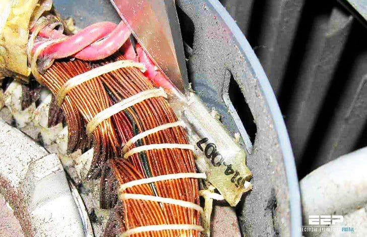
Thermal switch – built into the windings
Thermal protectors can also be built into the windings, see the illustration below. They operate as a sensitive power cut-out for both single and three-phase motors. In single-phase motors, up to a given motor size around 1.1 kW it can be mounted directly in the main circuit to serve as an on-winding protector.

Thermal protection to be connected in series with the winding or to a control circuit in the motor.

Klixon and Thermik are examples of thermal switch These devices are also called PTO (Protection Thermique à Ouverture).

Internal fitting
In single-phase motors one single thermal switch is used. In three-phase motors 2 thermal switches connected in series are placed between the phases of the motor. In that way all three phases are in contact with a thermal switch.
Thermal switches can be retrofitted on the coil end, but the result is an increased reaction time. The switches have to be connected to an external monitoring system. In that way the motor is protected against a slow overload. The thermal switches do not require an amplifier relay.
Thermal switches CANNOT protect against locked- rotor conditions.
How does a thermal switch function?
The curve on your right-hand side shows the resistance as a function of the temperature for a typical thermal switch. Depending on the thermal switch manufacturer, the curve changes.
TN is typically around 150 – 160°C.

Connection
Connection of a three-phase motor with built-in thermal switch and overload relay.
TP designation for the diagram
Protection according to the IEC 60034-11 standard: TP 111 (slow overload). In order to handle a locked-rotor, the motor has to be fitted with an overload relay.
 and manual reclosing (right)")
Where:
- S1 – On/off switch
- S2 – Off switch
- K1 – Contactor
- t – Thermal switch in motor
- M – Motor
- MV – Overload relay
Thermal switches can be loaded as followed:
Umax = 250 V AC
IN = 1.5 A
Imax = 5.0 A (cut-in and cut-out current)
Thermistors – also built into the windings
The second type of internal protection is the thermistors or Positive Temperature Coefficient sensors (PTC). The thermistors are built into the motor windings and protect the motor against locked-rotor conditions, continuous overload and high ambient temperature.
As a result of this change, the internal relays de-energize the control coil of the external line break contactor. As the motor cools and an acceptable motor winding temperature has been restored, the sensor resistance decreases to the reset level.
At this point, the module resets itself automatically, unless it was set up for manual reset. When the thermistors are retrofitted on the coil ends, the thermistors can only be classified as TP 111. The reason is that the thermistors do not have complete contact with the coil ends, and therefore, it cannot react as quickly as it would if they were fitted into the winding originally.

The thermistor temperature sensing system consists of positive temperature coefficient sensors (PTC) embedded in series of three – one between each phase – and a matched solid-state electronic switch in an enclosed control module. A set of sensors consists of three sensors, one per phase.

Only temperature sensitive. The thermistor has to be connected to a control circuit, which can convert the resistance signal, which again has to disconnect the motor. Used in three-phase motors.
The resistance in the sensor remains relatively low and constant over a wide temperature band and increases abruptly at a pre-determined temperature or trip point.
The relay opens the machine’s control circuit to shut down the protected equipment. When the winding temperature returns to a safe value, the module permits manual reset.
Reference // Grundfos – Motor Book (Download here)
Related electrical guides & articles


Edvard Csanyi
Hi, I'm an electrical engineer, programmer and founder of EEP - Electrical Engineering Portal. I worked twelve years at Schneider Electric in the position of technical support for low- and medium-voltage projects and the design of busbar trunking systems.I'm highly specialized in the design of LV/MV switchgear and low-voltage, high-power busbar trunking (<6300A) in substations, commercial buildings and industry facilities. I'm also a professional in AutoCAD programming.
Profile: Edvard Csanyi

need to know the adhesive you use tc secure a bimetal thermal switch on electri motor windings
Due to frequent burning of slip ring motor rotor winding want to ask you
“is there any overload protection can be provided for slip ring rotor winding?”
Sir,
can I ask some advise about the problem that we encounter. We have a 50 hp motor and the thermistor protective unit 220 volts coil that was installed was burned Now we have available only 110 volts coil. Our motor have a 3x PTC. My question is is there any voltage to be supplied in the PTC to be connected from T1 and T2 of the thermistor protected unit?
Can the wiring between the ptc sensor and the electrical control cabinet have intermediate splices? Would that affect the signal between the sender and the receiver?
Hello Edvard,
I am modifying a pedal car for my son (5) to run with a 24 vdc biphasic geared motor. I already damaged 2 motors (both of them run only at 12 vdc, I guess one phase is gone. and I know now why :-). I thought I was protecting it by using a 10-amp fuse connected to the battery but realized I could not be more wrong after reading your article. I don’t think I can modify the motor I am using to internally add any protection, but can you specify an external protection I can get?
Thanks,
Jesus Mayoral
P.D. The pedal car break pedaling back but I realized I can’t use the same system to break with the motor.
Wondering if I can swap out a two-lead thermal overload breaker for a three-wire one. This is on a table saw motor. Would it be legit to connect the two load wires (one for the motor and the other for the capacitor) and use a two-wire breaker?
Hello,
My washing machine motor has a black box above the coil with a 1 white wire enters and leaves on the other side. Looks like Thermal cut out . the connector coming from the coil is burnt. What can i do to have the machine up and running during lockdown?
Thermal Overloads are a control circuit interrupter. meaning power goes in and out, when temps get hot they open up and block power until it cools down. in the situation you’re describing, I would just jumper the 2 wires in the cabinet before it goes down to the motor and make sure nothing connected to the motor and wire leads are capped with wire nuts.
please let me know how we can select the value of thermistor PTC to fix if the re winder wound the machine without thermistor,i will be very much thankful to you. Mostly 11kw & 45 kw motor i need first if you have chart of the PTC for all machines it will be well and good.
Hi there,
What if I have a shorted motor and i need to rewind. The datasheet shows that the motor protection is PTC type. However, since there are many different types of PTC based on rated resistance. So, do i need to put a specific rated resistance PTC or will any type of PTC thermistor will do (which implies that the relay will be able to function since there will be abrupt change in temperature regardless of the rated resistance. Or the relay needs to be re-programmed to specifications of the new rated PTC). I have an ABB motor and now i do not know which PTC should i buy. I have checked the resistance of the existing PTC and it shows 200 Ohms. However, in the local market the readily available is only 100 Ohms PTC.
Thanks for the article. Only question I have is – Can over temp protection be used as overload. Our Australian standards require overload protection – I always put thermal overloads. However I have some motors with builtin over temp. Is this ever good enough?
Overload protection will protect the motor and the cable. Built-in over-temperature cannot protect the cable to the motor.
I stumbled into this article because I’m needing to replace a 1/4 hp blower motor that sits right under the fire box on a 50 year old fireplace insert. It is a TP motor and I was wondering if the TP was to protect the motor from the stove heat, but thanks to your info, I now know it’s to protect the motor from overheating and damaging the motor and possibly even causing a fire. I tried to get that motor rebuilt, but the electric shop told me that motor could not be rebuilt, drats! I’ll be lucky if the motor I replace it with will last that long. The old motor is still going, mostly because it has places you can oil it every few months during cold weather. If you have any recommendations for a replacement or extending the life of this motor, this old man would appreciate an email. Thanks for the article! JD
Espace Heater, like this like this
Hello Mr.adward , I am using a 3 phase motor WEG 200kw , it contain a built in winding temperature detector , thermistor (PTC) with Max. measuring voltage =2.5Vdc, 155 degree cel.
my question are :
1 / is this thermistor is cutting off at 155″C temperature ??
2 / is this sensor is operated normal if connect for a 20 meter cable distance ??
3 / is it necessary to connected it to a control circuit, which can convert the resistance signal, which again has to disconnect the motor ? or can connect directly to the contactor coil ??
thank you
Thank, very helpfull artical
Hello there,
I am looking for thermistor (winding sensor) for 19XR carrier compressor. Does anyone know part number for it or suggest any generic brand that I can use.
Thank you so much for your help
I am a bit confused. I am under the impression that a thermistor employs a resistor as the sensing element. Very similar to an RTD. What is the sensing element in a thermal protector? Would it be the difference in metals, per the bi-metal disc? This would be much like a thermocouple, but when I look at a Thermik spec sheet on a thermal protector, I do not see where the type of thermocouple is listed (K,N,T)? If we are talking about the sensing element only, would it be acceptable that a thermal protector employs a resistor as the sensing element, much like a thermistor or RTD?
Mr. Edvard, very nice article. I want to make a ppoint
We can use 2 PTC one for alarm & other for trip. PTC 110 can be for alarm & PTC130 for trip in same motor can be fitted & both purpose can be achieved.
For 3 phase machines if we use 2 different PTC then both alarm & trip can be achieved. In single motor we can emplyPTC110 for alarm & PTC130 for Trip for class F insulated motor. Hence both protections can be achieved.
Nice topic
Dear Edward
I am a regular reader of your articles. Thanks for your postings. This article is really informative
Good lucky for you…..thanks
nice one
Hello Mr.adward I m vipul an electrical engineer & a self employed in the field of motor winding since last 13 years. I would like to know how can we set winding data for different types of motors for both 1 ph -3 ph. I am also interested to know how different types of servomotor works.